LiftMaster SL595 SL595 Manual - Page 2
Table Of Contents - manual
 |
View all LiftMaster SL595 manuals
Add to My Manuals
Save this manual to your list of manuals |
Page 2 highlights
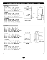
TABLE OF CONTENTS OPERATOR SPECIFICATIONS IMPORTANT NOTES Carton Inventory 2 Operator Dimensions and Horsepower Chart 3 UL325 Model Classifications 4 • BEFORE attempting to install, operate or maintain the operator, you MUST read and fully understand this manual and follow all safety instructions. OPERATOR WARNINGS Safety Installation Information 5 Suggested Entrapment Protection Device Locations 6 Safety Precautions for Open Roller Gates 7 Warning Sign Placement 7 • DO NOT attempt repair or service of your commercial door and gate operator unless you are an Authorized Service Technician. WARNING WIRING Mechanical Power Wiring Installation 8 INSTALWLATAIORN NING Pad Mounting (SL585 only 9 Post Mounting (SL585 & SL595 10 CAUTION Install Gate Bracket and Drive Chain 11 Available Conduit Access for the Electrical Box 12 On/Off Switch Power Wiring 12 CAUTION WARNING WEleActRricNal ING WARNING CAUTION Manual Disconnect 12 When you see these Safety Symbols and Signal Words on the AVERT ADJUSTMENT following pages, they will alert you to the possibility of SERIOUS Limit Switch Adjustment 13 INJURY or DEATH if you do not comply with the warnings that RPM Sensor Adjustment (Hall Effect 13 accompany them. The hazard may come from something Gate System Test Procedures 13 mechanical or from electric shock. Read the warnings carefully. AVERT Install Vent Plug 14 AVERTISSEMENT UL325 Entrapment Protection 14-15 AVERT Control Board Illustration 15 When you see this Signal Word on the following pages, it will alert you to the possibility of damage to your gate and/or the gate operator if you do not comply with the cautionary statements that Program Settings 16 accompany it. Read them carefully. AVERTISSEMENT Control Connection Diagrams 17 Radio Receiver 18-19 Accessory Wiring 19-20 CARTON INVENTORY ATTEN AVERT Earth Ground Rod Installation 21 ATTENTION AVER Sequenced Access Management System 22 Before beginning your installation check that all components were provided and received undamaged. Refer to list below OPERATION AND MAINTENANCE for factory provided parts. ATTE Operator Maintenance 23 AVERTISSEMENT Solenoid Actuated Brake 24 Friction Clutch 24 HARDWARE KIT SL585/SL595 (K77-34846) Control Board Programming and Features 24-25 AVER Troubleshooting 26-27 Self-Regulating Heater Accessory 28 Single Phase Wiring Diagram 29 Single Phase Schematic 30 Three Phase Wiring Diagram 31 Three Phase Schematic 32 DESCRIPTION Safety Gate Brochure Gate Bracket Take-Up Bolt Nickel Plated Chain #50 U-Bolt 2" 5/16-18 QTY. 1 2 2 1 4 REPAIR PARTS Repair Parts - Model SL585 33 Illustrated Parts - Model SL585 34 Repair Parts - Model SL595 35 Illustrated Parts - Model SL595 36 ADVERTENCIA Electrical Box 37 Safety Accessories for Secondary Entrapment Protection . . . . 38 NOTES 39 RECAWUARCRAINÓTYNPOLICY AND SERVICE 40 U-Bolt 3" 3/8-16 4 SAquDareVHeEadRSeTt SEcreNw 7C/16I"A-14 4 Hex Nut 1/2-13 4 Flange Nut 5/16"-18 8 PFFFLllloRaaaAcnttkgWWEDeWaaNssCaVhhsueehtArreE3r31/8//1UR82"/-""21"C6TEIAÓNDNCVIAERTENCIA 8 8 4 4 Antenna ADVERTENCIA1 PRECAUCIÓN 2
-
 1
1 -
 2
2 -
 3
3 -
 4
4 -
 5
5 -
 6
6 -
 7
7 -
 8
8 -
9
-
10
-
11
-
12
-
13
-
14
-
15
-
16
-
17
-
18
-
19
-
20
-
21
-
22
-
23
-
24
-
25
-
26
-
27
-
28
-
29
-
30
-
31
-
32
-
33
-
34
-
35
-
36
-
37
-
38
-
39
-
40
 |
 |
