Maytag MED6300TQ Use and Care Guide - Page 12
connection, Power, Use where local codes permit connecting cabinet-ground conductor, neutral wire.
 |
UPC - 883049060958
View all Maytag MED6300TQ manuals
Add to My Manuals
Save this manual to your list of manuals |
Page 12 highlights
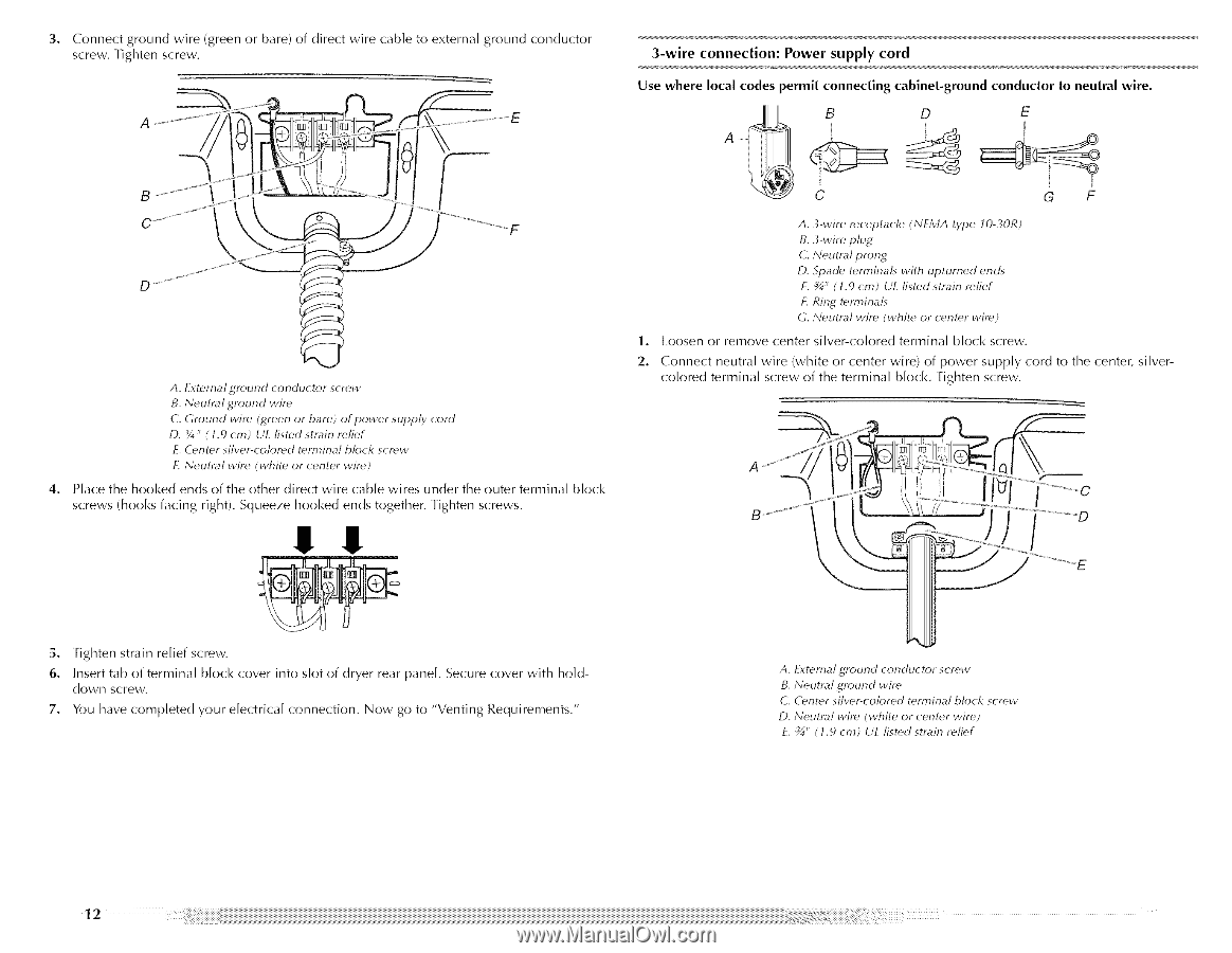
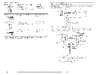
3, Connect ground wire (green or bare) of direct wire cable to external ground conductor screw. Tighten screw. 3-wire connection: Power supply cord Use where local codes permit connecting cabinet-ground conductor to neutral wire. A ...... / B C A. External ground conductor screw B. Neutral ground wire C. Ground wir_' Igreen or bare) of power supply cord D. _4" ( 1.9 cm) U[ listed strain reli_'f E. (_ulter silver-color_'d terminal block scr_'w L Neutral wire (white or center wir_') 4, Place the hooked ends of the other direct wire cable wires under the outer terminal screws (hooks facing right). Squeeze hooked ends together. Tighten screws. II block C G F A. 3-wire re'ceptacle (NFMA type lO-30R) B. 3-wire plug C. Neutral prong D. Spade' te'rminah with upturned ends E. _" (t.9 cm) U[ list_,d strain r_'lief £ Ring t_,rminals G. Neutral wire (white" or center wir_') 1. Loosen or remove center silver-colored terminal block screw. 2. Connect neutral wire (white or center wire) of power supply cord to the center, silvercolored terminal screw of the terminal block. Tighten screw. 5. Tighten strain relief screw. 6. Insert tab of terminal block cover into slot of dryer rear panel. Secure cover with hold- down screw. 7. You have completed your electrical connection. Now go to "Venting Requirements." A. [xternal ground conductor scr_'w B. Neutral ground wir_" C. C_'nte'r silver-colored terminal block screw D. Neutral wir_' (white of center wire) E. _" ( 1.9 cm) U[ listed strain relief
-
 1
1 -
2
-
3
-
4
-
5
-
6
-
 7
7 -
 8
8 -
 9
9 -
 10
10 -
 11
11 -
 12
12 -
 13
13 -
 14
14 -
 15
15 -
 16
16 -
 17
17 -
18
-
19
-
20
-
21
-
22
-
23
-
24
-
25
-
26
-
27
-
28
-
29
-
30
-
31
-
32
-
33
-
34
-
35
-
36
-
37
-
38
-
39
-
40
-
41
-
42
-
43
-
44
-
45
-
46
-
47
-
48
-
49
-
50
-
51
-
52
-
53
-
54
-
55
-
56
-
57
-
58
-
59
-
60
-
61
-
62
-
63
-
64
-
65
-
66
-
67
-
68
-
69
-
70
-
71
-
72
-
73
-
74
-
75
-
76
-
77
-
78
-
79
-
80
-
81
-
82
-
83
-
84
-
85
-
86
-
87
-
88
 |
 |