Maytag MED6300TQ Use and Care Guide - Page 9
Style 1: Power, Style, Direct
 |
UPC - 883049060958
View all Maytag MED6300TQ manuals
Add to My Manuals
Save this manual to your list of manuals |
Page 9 highlights
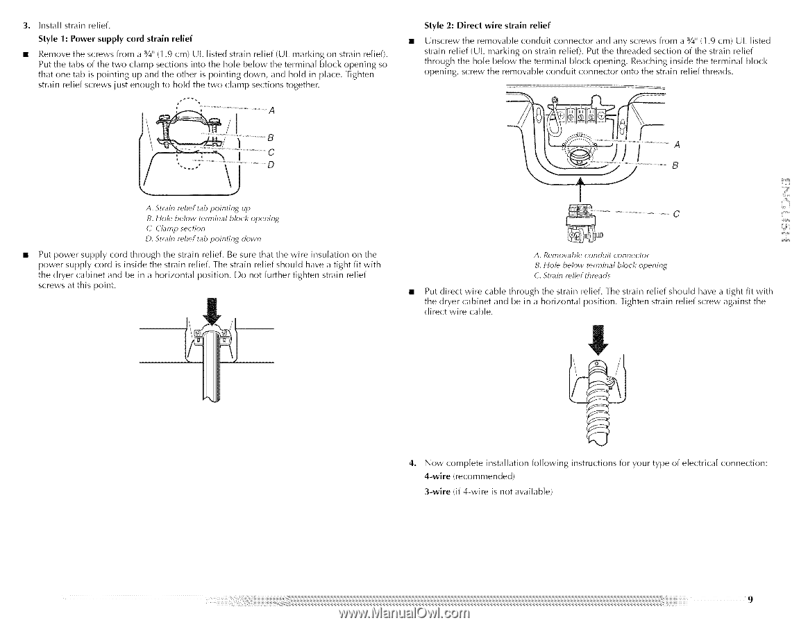
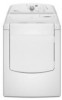
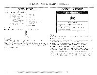
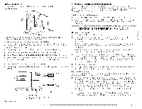
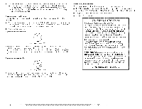
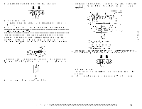
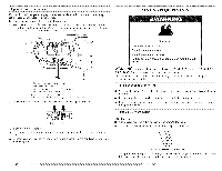
3. Install strain relief. Style 1: Power supply cord strain relief • Remove the screws from a %" (1.9 cm) UI. listed strain relief (UI marking on strain relief). Put the tabs of the two clamp sections into the hole below the terminal block opening so that one tab is pointing up and the other is pointing down, and hold in place. Tighten strain relief screws just enough to hold the two clam[) sections togethen Style 2: Direct wire strain relief Unscrew the removable conduit connector and any screws from a 3/4" (1.9 cm) U[. listed strain relief (UI. marking on strain relief). Put the threaded section of the strain relief through the hole below the terminal block opening. Reaching inside the terminal block opening, screw the removable conduit connector onto the strain relief threads. A. Strain relief tab pointing up B. Hole' below terminal block opening C. Clamp section D. Strain relief tab pointing down Put power supply cord through the strain relief. Be sure that the wire insulation on the power supply cord is inside the strain relief. The strain relief should have a tight fit with the dryer cabinet and be in a horizontal position. Do not further tighten strain relief screws at this point. A. Removable conduit connector B. Hole' below t_'rmina] block opening C. Strain relief threads Put direct wire cable through the strain relief. ]he strain relief should have a tight fit with the dryer cabinet and be in a horizontal position. Tighten strain relief screw against the direct wire cable. Now complete installation following 4-wire (recommended) 3-wire (if 4-wire is not available) instructions for your type of electrical connection:
-
 1
1 -
2
-
3
-
 4
4 -
 5
5 -
 6
6 -
 7
7 -
 8
8 -
 9
9 -
 10
10 -
 11
11 -
 12
12 -
 13
13 -
 14
14 -
15
-
16
-
17
-
18
-
19
-
20
-
21
-
22
-
23
-
24
-
25
-
26
-
27
-
28
-
29
-
30
-
31
-
32
-
33
-
34
-
35
-
36
-
37
-
38
-
39
-
40
-
41
-
42
-
43
-
44
-
45
-
46
-
47
-
48
-
49
-
50
-
51
-
52
-
53
-
54
-
55
-
56
-
57
-
58
-
59
-
60
-
61
-
62
-
63
-
64
-
65
-
66
-
67
-
68
-
69
-
70
-
71
-
72
-
73
-
74
-
75
-
76
-
77
-
78
-
79
-
80
-
81
-
82
-
83
-
84
-
85
-
86
-
87
-
88
 |
 |