Metabo CS 22-355 Operating Instructions - Page 14
Overview, Commissioning
 |
View all Metabo CS 22-355 manuals
Add to My Manuals
Save this manual to your list of manuals |
Page 14 highlights
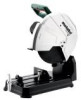
en ENGLISH Collect the particles generated at the source, avoid deposits in the surrounding area. Use suitable accessories for special work. In this way, fewer particles enter the environment in an uncontrolled manner. Use a suitable extraction unit. Reduce dust exposure with the following measures: - do not direct the escaping particles and the exhaust air stream at yourself or nearby persons or on dust deposits, - use an extraction unit and/or air purifiers, - ensure good ventilation of the workplace and keep clean using a vacuum cleaner. Sweeping or blowing stirs up dust. - Vacuum or wash the protective clothing. Do not blow, beat or brush. 5. Overview See page 2. 1 Wrench depot 2 Wrench for replacing cutting discs and adjustment work 3 Cutting depth limiter 4 Transportation lock 5 Lever 6 Cutting disc * 7 Safety cover 8 Spindle locking knob 9 Handle 10 Trigger switch 11 Safety switch (for protection against accidental start) 12 Spark deflector plate 13 Vice 14 Lever for quick adjustment 15 Crank 16 Stopper 17 Screws (for setting cutting angle and maximum clamping width) * not in scope of delivery 6. Commissioning Before plugging in, check to see that the rated mains voltage and mains frequency, as specified on the rating label, match your power supply. Always install an RCD with a max. trip current of 30 mA upstream. The machine can be supplied only with the mains voltage and frequency specified on the type plate. When, for example, a 120 V machine is supplied with 230 V of mains voltage, the cutting discs and the machine can be damaged by surpassing the max. rpm. All screws must be screwed tight. Screw the screw tight with the provided wrench to fasten the cutting disc and check if all other screws are also screwed tight. Spark deflector plate (12): Before commissioning the spark deflector plate, tilt it to the mark. 7. Use 7.1 Setting cutting depth For presetting the desired cutting depth, e.g. for several cuts with the same cutting depth. Setting the cutting depth limiter (3): - Free the lock nut. - Set the hexagon screw for the desired cutting depth. - Retighten the lock nut. 7.2 Vice Clamp the workpiece tightly into the vice (13). Setting the cutting angle: - Loosen the two screws (17) on the stopper (16). - Set the desired cutting angle. - Retighten the two screws (17). Configuring the maximum clamping width: The stopper can be set for 3 positions. - Additionally, remove the two screws (17). - Shift the stopper (16) to the rear / middle / forward position. - Fasten the stopper (16) again with the two screws (17). Clamping the workpiece: - For quick adjustment, turn the lever (14) forwards and push the crank (15) towards the workpiece. - Push the lever (14) backwards and tight turn the crank (15) clockwise to clamp the workpiece. 7.3 Cutting through a workpiece Danger of crushing! Do not reach into the area of the joint when lowering the lever! • Do not begin cutting until the machine has reached its maximum rpm. • Slowly lower the cutting disc onto the workpiece and conduct the cut with little contact pressure. • After finishing the job, put the lever into the starting position. • After a complete cut, switch off the machine, allow the motor to come to a complete standstill and only then prepare the next cutting job. The removal or insertion of workpieces while the cutting disc is rotating can lead to injury. • Do not work with too much contact pressure, since the cutting disc can otherwise quickly become worn out, or the machine or workpiece can be damaged. 7.4 Switching on and off Switching on: Press and hold safety switch (11), press the trigger (10). Switching off: release the trigger switch (10). 14
-
 1
1 -
2
-
3
-
4
-
5
-
6
-
7
-
8
-
 9
9 -
 10
10 -
 11
11 -
 12
12 -
 13
13 -
 14
14 -
 15
15 -
 16
16 -
 17
17 -
 18
18 -
 19
19 -
20
-
21
-
22
-
23
-
24
-
25
-
26
-
27
-
28
-
29
-
30
-
31
-
32
-
33
-
34
-
35
-
36
-
37
-
38
-
39
-
40
-
41
-
42
-
43
-
44
-
45
-
46
-
47
-
48
-
49
-
50
-
51
-
52
-
53
-
54
-
55
-
56
-
57
-
58
-
59
-
60
-
61
-
62
-
63
-
64
-
65
-
66
-
67
-
68
-
69
-
70
-
71
-
72
-
73
-
74
-
75
-
76
-
77
-
78
-
79
-
80
-
81
-
82
-
83
-
84
-
85
-
86
-
87
-
88
-
89
-
90
-
91
-
92
-
93
-
94
-
95
-
96
 |
 |
