NEC PX-50VP1A 42PD2/50PD1 - Page 52
Application, Connections
 |
View all NEC PX-50VP1A manuals
Add to My Manuals
Save this manual to your list of manuals |
Page 52 highlights
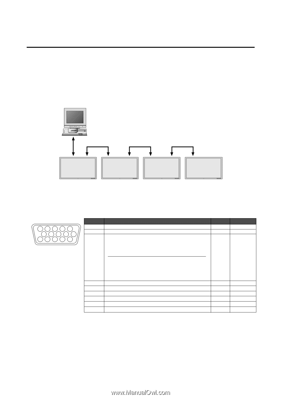
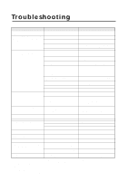
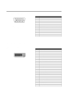
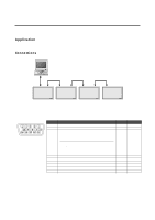
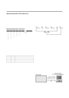
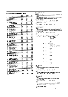
Function and Pin Configuration of the External Control Connector Application These specifications are applicable to NEC plasma monitors (including 42- and 50-inch types) and communications control from external equipment. Connections Connections should be made as described below. External equipment e.g., Personal computer PDP1 Display PDP2 Display PDP3 Display PDP4 Display *A maximum of 4 units can used with a cascade connection. 1) Display-side connector: EXTERNAL CONTROL connector EXTERNAL CONTROL 543 2 1 10 9 8 7 6 15 14 13 12 11 Pin No. 1 to 3 4 5 and 14 Not used Power ON/OFF Function Input switching The input mode is switched by the combination of pin numbers 5 and 14. Input VIDEO RGB1 RGB2 RGB3 Pin No. 5 Open Ground Open Ground Pin No. 14 Open Open Ground Ground 6 to 8 9 and 10 11 12 13 15 Not used Ground TXD (RS-232C) RTS RXD (RS-232C) CTS Open Established ON OFF 2) External equipment side connector: Serial port (RS-232C) connector See the specifications of the connected equipment for information about the type of connector and pin assignment. 52
-
 1
1 -
2
-
3
-
4
-
5
-
6
-
7
-
8
-
9
-
10
-
11
-
12
-
13
-
14
-
15
-
16
-
17
-
18
-
19
-
20
-
21
-
22
-
23
-
24
-
25
-
26
-
27
-
28
-
29
-
30
-
31
-
32
-
33
-
34
-
35
-
36
-
37
-
38
-
39
-
40
-
41
-
42
-
43
-
44
-
45
-
46
-
 47
47 -
 48
48 -
 49
49 -
 50
50 -
 51
51 -
 52
52 -
 53
53 -
 54
54 -
 55
55 -
 56
56 -
 57
57 -
58
-
59
-
60
-
61
-
62
-
63
-
64
 |
 |