Netgear FSM726S FSM726S User Manual - Page 107
Appendix F: Cabling Guidelines
 |
UPC - 606449023091
View all Netgear FSM726S manuals
Add to My Manuals
Save this manual to your list of manuals |
Page 107 highlights
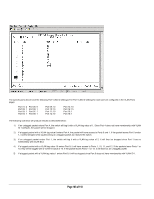
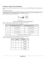
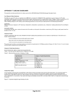
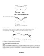
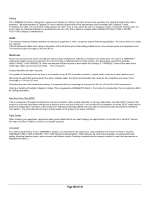
APPENDIX F: CABLING GUIDELINES This appendix provides specifications for cables used with the NETGEAR Model FSM726S Managed Stackable Switch. Fast Ethernet Cable Guidelines Fast Ethernet uses UTP cable, as specified in the IEEE 802.3u standard for 100BASE-TX.The specification requires Category 5 UTP cable consisting of either two-pair or four-pair twisted insulated copper conductors bound in a single plastic sheath. Category 5 cable is certified up to 100 MHz bandwidth. 100BASE-TX operation uses one pair of wires for transmission and the other pair for receiving and for collision detection. When installing Category 5 UTP cabling, use the following guidelines to ensure that your cables perform to the following specifications: Certification Make sure that your Category 5 UTP cable has completed the Underwriters' Laboratories (UL) or Electronic Testing Laboratories (ETL) certification process. Termination method To minimize cross-talk noise, maintain the twist ratio of the cable up to the point of termination; untwist at any RJ-45 plug or patch panel should not exceed 0.5 inch (1.5 cm). Category 5 Cable Category 5 distributed cable that meets ANSI/EIA/TIA-568-A building wiring standards can be a maximum of 328 feet (ft) or 100 meters (m) in length, divided as follows: 20 ft (6 m) between the hub and the patch panel (if used) 295 ft (90 m) from the wiring closet to the wall outlet 10 ft (3 m) from the wall outlet to the desktop device The patch panel and other connecting hardware must meet the requirements for 100 Mbps operation (Category 5). Only 0.5 inch (1.5 cm) of untwist in the wire pair is allowed at any termination point. Category 5 Cable Specifications Ensure that the fiber cable is crossed over to guarantee link. Table F-1 lists the electrical requirements of Category 5 UTP cable. Table F-1. Electrical Requirements of Category 5 Cable Specifications Number of pairs Impedance Mutual capacitance at 1 KHz Maximum attenuation (dB per 100 m, at 20° C) NEXT loss (dB minimum) Category 5 Cable Requirements Four 100 Ω ± 15% ≤5.6 nF per 100 m at 4 MHz: 8.2 at 31 MHz: 11.7 at 100 MHz: 22.0 at 16 MHz: 44 at 31 MHz: 39 at 100 MHz: 32 Twisted Pair Cables For two devices to communicate, the transmitter of each device must be connected to the receiver of the other device. The crossover function is usually implemented internally as part of the circuitry in the device. Computers and workstation adapter cards are usually media-dependent interface ports, called MDI or uplink ports. Most repeaters and switch ports are configured as media-dependent interfaces with built-in crossover ports, called MDI-X or normal ports. Auto Uplink technology automatically senses which connection, MDI or MDI-X, is needed and makes the right connection. Figure F-1 illustrates straight-through twisted pair cable. Page 107 of 110
-
 1
1 -
2
-
3
-
4
-
5
-
6
-
7
-
8
-
9
-
10
-
11
-
12
-
13
-
14
-
15
-
16
-
17
-
18
-
19
-
20
-
21
-
22
-
23
-
24
-
25
-
26
-
27
-
28
-
29
-
30
-
31
-
32
-
33
-
34
-
35
-
36
-
37
-
38
-
39
-
40
-
41
-
42
-
43
-
44
-
45
-
46
-
47
-
48
-
49
-
50
-
51
-
52
-
53
-
54
-
55
-
56
-
57
-
58
-
59
-
60
-
61
-
62
-
63
-
64
-
65
-
66
-
67
-
68
-
69
-
70
-
71
-
72
-
73
-
74
-
75
-
76
-
77
-
78
-
79
-
80
-
81
-
82
-
83
-
84
-
85
-
86
-
87
-
88
-
89
-
90
-
91
-
92
-
93
-
94
-
95
-
96
-
97
-
98
-
99
-
100
-
101
-
 102
102 -
 103
103 -
 104
104 -
 105
105 -
 106
106 -
 107
107 -
 108
108 -
 109
109 -
 110
110
 |
 |