Netgear FSM726S FSM726S User Manual - Page 19
Step 3: Installing a GBIC Module, Step 4: Connecting Switches to the Stack's Backplane
 |
UPC - 606449023091
View all Netgear FSM726S manuals
Add to My Manuals
Save this manual to your list of manuals |
Page 19 highlights
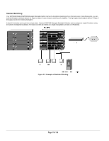
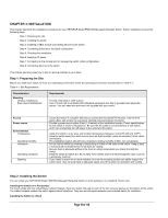
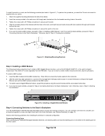
To install the switch in a rack, use the following procedure (and refer to Figure 4-1). To perform this procedure, you need the 19-inch rack-mount kit supplied with your switch. 1. Attach the supplied mounting brackets to the side of the switch. 2. Insert the screws provided in the rack-mount kit through each bracket and into the bracket mounting holes in the switch. 3. Tighten the screws with a #1 Phillips screwdriver to secure each bracket. 4. Align the mounting holes in the brackets with the holes in the rack, and insert two pan-head screws with nylon washers through each bracket and into the rack. 5. Tighten the screws with a #2 Phillips screwdriver to secure the switch in the rack. 6. If you want to install a GBIC module, proceed to "Step 3: Installing a GBIC Module," next. If you want to stack switches, proceed to "Step 4: Connecting Switches to the Stack's Backplane," Otherwise, skip to "Step 5: Checking the Installation." Figure 4-1. Attaching Mounting Brackets Step 3: Installing a GBIC Module The following procedure describes how to install a GBIC Gigabit Ethernet module, such as the NETGEAR AGM721F, in the switch's Gigabit module bays. The AGM721F is sold separately from the FMS726S. If you do not want to install a GBIC module at this time, skip this procedure. To install a GBIC module: 7. Insert the GBIC module into the GBIC module bay. Press firmly to ensure the module seats into the connector. 8. After the switch has been powered on, use one of the management interfaces (web browser or console interface) to configure the Gigabit Ethernet port with the GBIC module installed to the GBIC option. 9. To install a second Gigabit Ethernet module, repeat this procedure using the second module and the unoccupied module bay. 10. If you want to stack switches, proceed to "Step 4: Connecting Switches to the Stack's Backplane," next. Otherwise, skip to "Step 5: Checking the Installation." Figure 4-2. Installing a Gigabit Ethernet Module Step 4: Connecting Switches to the Stack's Backplane Your NETGEAR Model FSM726S Managed Stackable Switch provides two stacking connectors. You can use these connectors to cascade up to six switches together to create one large virtual switch (for more information, see "Stacked Switching" on page 17). Observe the following guidelines when installing the switches in a stacked configuration. Connecting Stacking Ports When connecting two FSM726S Managed Stackable Switches, one stacking cable connects the stacking port on one switch to the stacking port on the other switch. Page 19 of 110
-
 1
1 -
2
-
3
-
4
-
5
-
6
-
7
-
8
-
9
-
10
-
11
-
12
-
13
-
 14
14 -
 15
15 -
 16
16 -
 17
17 -
 18
18 -
 19
19 -
 20
20 -
 21
21 -
 22
22 -
 23
23 -
 24
24 -
25
-
26
-
27
-
28
-
29
-
30
-
31
-
32
-
33
-
34
-
35
-
36
-
37
-
38
-
39
-
40
-
41
-
42
-
43
-
44
-
45
-
46
-
47
-
48
-
49
-
50
-
51
-
52
-
53
-
54
-
55
-
56
-
57
-
58
-
59
-
60
-
61
-
62
-
63
-
64
-
65
-
66
-
67
-
68
-
69
-
70
-
71
-
72
-
73
-
74
-
75
-
76
-
77
-
78
-
79
-
80
-
81
-
82
-
83
-
84
-
85
-
86
-
87
-
88
-
89
-
90
-
91
-
92
-
93
-
94
-
95
-
96
-
97
-
98
-
99
-
100
-
101
-
102
-
103
-
104
-
105
-
106
-
107
-
108
-
109
-
110
 |
 |
