Onkyo TX-SR601 Owner Manual - Page 20
INPUT 2 jacks.
 |
View all Onkyo TX-SR601 manuals
Add to My Manuals
Save this manual to your list of manuals |
Page 20 highlights
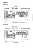
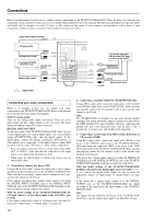
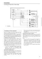
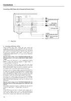
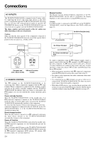
Connections 8. TV monitor or projector (MONITOR OUT) 7. DVD recorder, other digital video recording device (VIDEO 2) ANTENNA AM COMPONENT VIDEO INPUT 2 INPUT 1 OUTPUT Y PB FM 75 ZONE 2 LINE OUT L Digital audio input (coaxial) TX-SR701/701E only Video input S Video input L (white) Analog audio input R (red) L (white) PR DIGITAL IN OUT OPTICAL 2 1 OPTICAL COAXIAL VIDEO 3 IN VIDEO 2 OUT IN R VIDEO 1 OUT IN DVD IN REMOTE CONTRO MONITOR OUT ZON V IN GND L S IN COAXIAL IN OUT IN IN OUT IN OUT IN FRONT SURR CENTER L R PHONO CD TAPE VIDEO 3 VIDEO 2 VIDEO 1 R DVD SUB WOOFER Component video input Video input S Video input Analog audio output R (red) S Video output Video output 7. Connecting a DVD recorder or other digital video recording device (VIDEO 2) Using RCA video cables, connect the video output jack (composite) of the device to the VIDEO 2 V IN jack of the TX-SR701/701E/ 601/601E and connect the video input jack of the device to the VIDEO 2 V OUT jack of the TX-SR701/701E/601/601E. Or if the device has S video input and output jacks, using S video cables, connect the S video output jack of the device to the VIDEO 2 S IN jack of the TX-SR701/701E/601/601E and connect the video input jack of the device to the VIDEO 2 S OUT jack of the TX-SR701/ 701E/601/601E. Or if the device has component video outputs, connect them to the COMPONENT VIDEO INPUT 1 or 2 jacks on the TX-SR701/701E/601/601E. With the initial settings of the TX-SR701/701E/601/601E, the VIDEO 2 input source is set for the COMPONENT VIDEO INPUT 2 jacks. If you connect the device to the COMPONENT VIDEO INPUT 1 jacks, this must be changed at "Input Setup" → "Component Video" (see page 53). Using RCA audio cables, connect the audio output jacks of the device to the VIDEO 2 IN audio jacks of the TX-SR701/701E/601/ 601E and connect the audio input jacks of the device to the VIDEO 2 OUT audio jacks of the TX-SR701/701E/601/601E. Make sure that you properly connect the left channels to the L jacks and the right channels to the R jacks. If the device has a digital output, connect it to either the DIGITAL IN COAXIAL jack or the DIGITAL IN OPTICAL jack of the TXSR701/701E/601/601E depending on the type of connector on the device. With the initial settings of the TX-SR701/701E/601/601E, nothing is allocated as the digital input source for VIDEO 2 (----). If you connect the digital audio output, be sure to make the appropriate changes at "Input Setup" → "Digital Input" (see page 52). If the device has a digital input, connect it to the DIGITAL OUTPUT jack of the TX-SR701/701E/601/601E for digital recording of the signal from the digital input of the TX-SR701/ 701E/601/601E. 20 : Signal flow Note: The output from the DIGITAL OUT jack of the TX-SR701/701E/ 601/601E is only the digital signal input to the DIGITAL IN jack. 8. Connecting a television monitor or projector (MONITOR OUT) The TX-SR701/701E/601/601E is equipped with a simple Y/C separate circuit and simple Y/C mixed circuit. Since both the signal from the S and V inputs are output to the MONITOR OUT S output, if the television or projector is equipped with an S video input, it is unnecessary to connect the video connectors. If it is equipped with only a video input, connect it to the MONITOR OUT V output. Using an RCA video cable, connect the video input jack (composite) of the device to the MONITOR OUT V jack of the TXSR701/701E/601/601E. Or if the device has an S video input jack, connect it to the MONITOR OUT S jack of the TX-SR701/701E/ 601/601E using an S video cable. Or if the device has component video inputs, connect them to the bank of COMPONENT VIDEO OUTPUT jacks on the TX-SR701/701E/601/601E. Note: Note that the Setup Menu will only be displayed on the monitor connected to MONITOR OUT (S or V) and not those connected to the COMPONENT VIDEO OUTPUT jacks.
-
 1
1 -
2
-
3
-
4
-
5
-
6
-
7
-
8
-
9
-
10
-
11
-
12
-
13
-
14
-
 15
15 -
 16
16 -
 17
17 -
 18
18 -
 19
19 -
 20
20 -
 21
21 -
 22
22 -
 23
23 -
 24
24 -
 25
25 -
26
-
27
-
28
-
29
-
30
-
31
-
32
-
33
-
34
-
35
-
36
-
37
-
38
-
39
-
40
-
41
-
42
-
43
-
44
-
45
-
46
-
47
-
48
-
49
-
50
-
51
-
52
-
53
-
54
-
55
-
56
-
57
-
58
-
59
-
60
-
61
-
62
-
63
-
64
-
65
-
66
-
67
-
68
-
69
-
70
-
71
-
72
-
73
-
74
-
75
-
76
-
77
-
78
-
79
-
80
 |
 |
