Onkyo TX-SR601 Owner Manual - Page 22
Operating components not reached by the remote, controller signals IR - receiver
 |
View all Onkyo TX-SR601 manuals
Add to My Manuals
Save this manual to your list of manuals |
Page 22 highlights
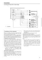
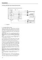
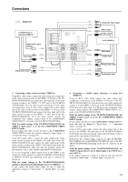
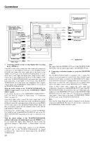
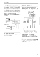
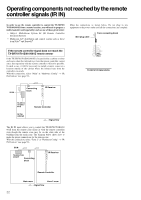
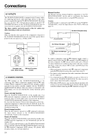
Operating components not reached by the remote controller signals (IR IN) In order to use the remote controller to control the TX-SR701/ 701E/601/601E from a remote location, you will need to prepare a multi-room kit (sold separately) such as one of those given below: • Onkyo's Multi-Room System kit (IR Remote Controller Extension System) • Multiroom A/V distribution and control system such as those from Niles® and Xantech® If the remote controller signal does not reach the TX-SR701/701E/601/601E remote sensor If the TX-SR701/701E/601/601E is located inside a cabinet or other enclosure where the infrared rays from the remote controller cannot enter, then operation with the remote controller will not be possible. In such a case, it will be necessary to install a remote sensor at a location outside of the cabinet where the infrared rays from the controller can reach. With this connection, select "Main" at "Hardware Config" → "IR IN Position" (see page 55). Make the connections as shown below. Do not plug in any equipment to the power outlet until all the connections are complete. Mini plug cable From connecting block REMOTE CONTROL MONITOR OUT V ZONE 2 12 V TRIGGER OUT S IR IN TX-SR701/701E/601/601E IR IN Connecting block IR Receiver TX-SR701/ 701E/601/ 601E Remote Controller In the cabinet : Signal flow The IR IN input allows you to control the TX-SR701/701E/601/ 601E from the remote zone (Zone 2) with the remote controller even though the remote zone may be on the other side of the building from the main zone. The diagram below shows how to make the proper connections for the remote zone. With this connection, select "Zone 2" at "Hardware Config" → "IR IN Position" (see page 55). IR IN TX-SR701/701E/ 601/601E Connecting block IR Receiver Remote Controller Main room Zone 2 room : Signal flow 22
-
 1
1 -
2
-
3
-
4
-
5
-
6
-
7
-
8
-
9
-
10
-
11
-
12
-
13
-
14
-
15
-
16
-
 17
17 -
 18
18 -
 19
19 -
 20
20 -
 21
21 -
 22
22 -
 23
23 -
 24
24 -
 25
25 -
 26
26 -
 27
27 -
28
-
29
-
30
-
31
-
32
-
33
-
34
-
35
-
36
-
37
-
38
-
39
-
40
-
41
-
42
-
43
-
44
-
45
-
46
-
47
-
48
-
49
-
50
-
51
-
52
-
53
-
54
-
55
-
56
-
57
-
58
-
59
-
60
-
61
-
62
-
63
-
64
-
65
-
66
-
67
-
68
-
69
-
70
-
71
-
72
-
73
-
74
-
75
-
76
-
77
-
78
-
79
-
80
 |
 |