Onkyo TX-SR601 Owner Manual - Page 24
Ac Outlets, Remote Control - remote code
 |
View all Onkyo TX-SR601 manuals
Add to My Manuals
Save this manual to your list of manuals |
Page 24 highlights
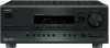
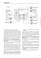
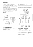
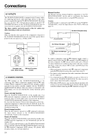
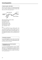
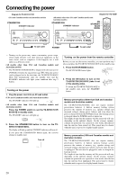
Connections AC OUTLETS The TX-SR701/701E/601/601E is equipped with AC mains outlets for connecting the power cords from other devices so that their power is supplied through the TX-SR701/701E/601/601E. By doing this, you can leave the connected device turned on and have the STANDBY/ON button on the TX-SR701/701E/601/601E turn on and off the device together with the TX-SR701/701E/601/601E. The shape, number, and total capacity of the AC outlets may differ depending on the area of purchase. Caution: Make sure that the total capacity of the components connected to the TX-SR701/701E/601/601E does not exceed the capacity that is printed on the rear panel (e.g., TOTAL 120W). Dimmer function The Dimmer function (display brightness adjustment) of the TXSR701/701E/601/601E can be used to synchronize the display brightness on the connected device using the connection. Caution: If an MD recorder is connected to the TAPE jack on the TX-SR701/ 701E/601/601E, switch the Input Selector from TAPE to MD (see page 43). TX-SR701/701E/601/601E connector AC OUTLETS AC OUTLETS AC 230-240V 50 Hz SWITCHED TOTAL 100W MAX. AC 120V 60 Hz SWITCHED TOTAL 120W 1A MAX. European and USA and Canadian some Asian models models REMOTE CONTROL The terminal on the TX-SR701/701E/601/601E is for connecting other Onkyo components equipped with the same terminal. When a component is connected to the terminal, it can be operated by the remote controller supplied with the TX-SR701/ 701E/601/601E. In addition, when you connect a component to the terminal, you can also perform the system operations given below. Power on/ready function When the TX-SR701/701E/601/601E is in the standby state, if an -connected component is turned on, the TX-SR701/701E/601/ 601E also turns on and the input source selected at the TX-SR701/ 701E/601/601E automatically switches to that component. Be aware that this function will not work if the power cord for the connected component is connected to the AC OUTLET on the TXSR701/701E/601/601E, or if the TX-SR701/701E/601/601E has already been turned on. Direct change function When the play button is pressed at an -connected component, the input source selected at the TX-SR701/701E/601/601E automatically changes to that component. Power off function When the TX-SR701/701E/601/601E is placed in the standby state, all -connected components are also automatically put into the standby state. Also, if you press the ON button on the TX-SR701/701E/601/601E remote controller while the TX-SR701/701E/601/601E is turned on, all -connected components (DVD players, CD players, MD recorders, tuners, etc.) are also turned on. 24 Ex: Onkyo CD player connector Ex: Onkyo cassette tape deck To connect components using the terminal, simply connect a remote control cable from this terminal to the terminal of the other component. An remote control cable with a 1/8-inch (3.5-mm) miniature two-conductor plug comes with every cassette tape deck, compact disc player, MD recorder, and DVD player that has an terminal. • When performing operations with -connected components using the system, do not use the remote zone (Zone 2) . • For remote control operation, the audio connection cables must also be connected. • If a component has two terminals, you can use either one to connect to the TX-SR701/701E/601/601E. The other one can be used to daisy chain with another component. • With Onkyo DVD players, you can enter the pre-program code so that you can operate the DVD player directly with the remote controller without connecting the terminals (see page 67).
-
 1
1 -
2
-
3
-
4
-
5
-
6
-
7
-
8
-
9
-
10
-
11
-
12
-
13
-
14
-
15
-
16
-
17
-
18
-
 19
19 -
 20
20 -
 21
21 -
 22
22 -
 23
23 -
 24
24 -
 25
25 -
 26
26 -
 27
27 -
 28
28 -
 29
29 -
30
-
31
-
32
-
33
-
34
-
35
-
36
-
37
-
38
-
39
-
40
-
41
-
42
-
43
-
44
-
45
-
46
-
47
-
48
-
49
-
50
-
51
-
52
-
53
-
54
-
55
-
56
-
57
-
58
-
59
-
60
-
61
-
62
-
63
-
64
-
65
-
66
-
67
-
68
-
69
-
70
-
71
-
72
-
73
-
74
-
75
-
76
-
77
-
78
-
79
-
80
 |
 |