Panasonic AJHD1700P AJHD1700 User Guide - Page 82
<basic>, Monitor, Sd Sdi Monitor And Video
 |
View all Panasonic AJHD1700P manuals
Add to My Manuals
Save this manual to your list of manuals |
Page 82 highlights
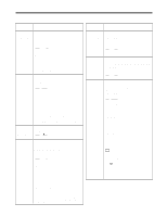
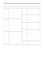
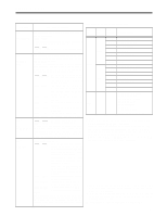
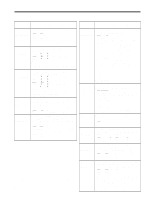
Setup menus (continued) No./Item Description of setting 006 DISPLAY SEL 007 CHARA H-POS 008 CHARA V-POS • The following mode displays appear depending on the format used. DVCPRO HD-LP > DVCPRO_HD-LP DVCPRO HD > DVCPRO_HD DVCPRO50 > DVCPRO_50 DVCPRO > DVCPRO DV > DV DVCAM > DVCAM • When setting 2 (T&S&M) is selected, an error message appears if a warning or error has occurred. • REC TIME and REC DATE are displayed only during DV or DVCAM format playback. The operation mode is displayed when the DVCPRO HD-LP, DVCPRO HD, DVCPRO50 or DVCPRO format is used. For setting the horizontal positions of the characters for the time code and other superimposed displays of the HD SDI MONITOR, SD SDI MONITOR and VIDEO OUT3 connectors. 0000 0 : : 0006 6 : : 0037 37 When this menu item has been set, the displays are output to the VIDEO OUT3 connector in the DISPLAY SEL status even when the SUPER OFF setting is established. However, if the menu has been exited, the SUPER OFF or ON setting is followed. Furthermore, CHARA TYPE is output to the VIDEO OUT3 connector as per the menu setting. For setting the vertical positions of the characters for the time code and other superimposed displays of the HD SDI MONITOR, SD SDI MONITOR and VIDEO OUT3 connectors. 0000 0 : : 0023 23 : : 0032 32 When this menu item has been set, the displays are output to the VIDEO OUT3 connector in the DISPLAY SEL status even when the SUPER OFF setting is established. However, if the menu has been exited, the SUPER OFF or ON setting is followed. Furthermore, CHARA TYPE is output to the VIDEO OUT3 connector as per the menu setting. No./Item Description of setting 009 CHARA TYPE 010*1 MONI CONTROL For setting the display type for the superimposed displays and for the HD SDI MONITOR, SD SDI MONITOR and VIDEO OUT3 connectors as well as for the SETUP MENU, etc. 0000 WHITE: White characters on a black background. 0001 W/OUT: White characters with black borders. For setting whether to forcibly set the recorder to the EE mode and output the player's playback signals to the monitor if the PLAYER button on the recorder is pressed when the monitor is connected only to the recorder during deck-to-deck editing. 0000 MANU: The recorder is not forcibly set to the EE mode. 0001 AUTO: The recorder is forcibly set to the EE mode, and the player's playback signals are output. 011 CU-ROLL TIME For setting the preroll time in the MULTI CUE mode. Any time from 0 to 15 seconds can be set in 1- second increments. 0000 0s: : : 0005 5s: : : 0015 15s: 015 AUTO STEP For selecting the save processing to be conducted when the memory capacity, which enables up to 99 warning messages to be saved, has been exceeded while the error log function is operating. 0000 OFF: 99 messages are set as the upper limit, and any more warning messages which subsequently occur are not saved in the memory. 0001 ON: 99 messages are saved, and the next warning message that has subsequently occurred is saved as No.99. The warning messages already saved are each shifted down by one number in succession. 020*2 SYS FORMAT For selecting the VTR's recording format. 0000 1080i: The 1080i format is selected. 0001 720p: The 720p format is selected. *1: This item is not displayed when the 23/24 Hz or 25 Hz (HD or SD) mode has been selected as the system menu item No.25 (SYSTEM FREQ) setting. *2: This item is not displayed when the 23/24 Hz, 25 Hz (HD or SD) or 50 Hz mode has been selected as the system menu item No.25 (SYSTEM FREQ) setting. The underlining (__) denotes the factory setting mode. 82
-
 1
1 -
2
-
3
-
4
-
5
-
6
-
7
-
8
-
9
-
10
-
11
-
12
-
13
-
14
-
15
-
16
-
17
-
18
-
19
-
20
-
21
-
22
-
23
-
24
-
25
-
26
-
27
-
28
-
29
-
30
-
31
-
32
-
33
-
34
-
35
-
36
-
37
-
38
-
39
-
40
-
41
-
42
-
43
-
44
-
45
-
46
-
47
-
48
-
49
-
50
-
51
-
52
-
53
-
54
-
55
-
56
-
57
-
58
-
59
-
60
-
61
-
62
-
63
-
64
-
65
-
66
-
67
-
68
-
69
-
70
-
71
-
72
-
73
-
74
-
75
-
76
-
 77
77 -
 78
78 -
 79
79 -
 80
80 -
 81
81 -
 82
82 -
 83
83 -
 84
84 -
 85
85 -
 86
86 -
 87
87 -
88
-
89
-
90
-
91
-
92
-
93
-
94
-
95
-
96
-
97
-
98
-
99
-
100
-
101
-
102
-
103
-
104
-
105
-
106
-
107
-
108
-
109
-
110
-
111
-
112
-
113
-
114
-
115
-
116
-
117
-
118
-
119
-
120
-
121
-
122
-
123
-
124
-
125
-
126
-
127
-
128
-
129
-
130
-
131
-
132
-
133
-
134
 |
 |
