Panasonic PTDS8500U PTDS8500U User Guide - Page 34
Connections, Before connection to the projector
 |
UPC - 885170010994
View all Panasonic PTDS8500U manuals
Add to My Manuals
Save this manual to your list of manuals |
Page 34 highlights
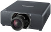
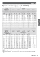
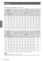
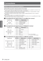
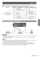
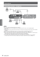
Getting Started Connections Before connection to the projector zzRead carefully the instruction manual for the device to be connected. zzTurning off the power switch of the devices before connecting cables. zzIf any connection cable is not supplied with the device, or if no optional cable is available for connection of the device, prepare a necessary system connection cable to suit the device. zzVideo signals containing too much jitter may cause the images on the screen to randomly wobble or wafture. In this case, a time base corrector (TBC) must be connected. zzThe projector accepts the following signals: VIDEO, S-VIDEO, analogue-RGB (with TTL sync. Level) and digital signal. zzSome computer models are not compatible with the projector. zzWhen using long cables to connect with each of equipment to the projector, there is a possibility that the image will not be output correctly unless a compensator is used. JJPin assignments and signal names of terminal Outside view Pin No. Signal names GND (luminance signal) GND (color signal) Luminance signal Color signal JJPin assignments and signal names of terminal Outside view Pin No. Signal names R/PR G/G SYNC/Y B/PB DDC data HD/SYNC VD DDC clock , : Not assigned - , , : GND terminals JJPin assignments and signal names of terminal Outside view Odd-numbered pins to Even-numbered pins to Pin No. Signal names T.M.D.S data 2+ T.M.D.S data 2T.M.D.S data 1 shield T.M.D.S data 0+ T.M.D.S data 0T.M.D.S clock shield CEC SCL DDC/CEC GND Hot plug detection Pin No. Signal names T.M.D.S data 2 shield T.M.D.S data 1+ T.M.D.S data 1T.M.D.S data 0 shield T.M.D.S clock + T.M.D.S clock - - SDA +5V 34 - ENGLISH
-
 1
1 -
2
-
3
-
4
-
5
-
6
-
7
-
8
-
9
-
10
-
11
-
12
-
13
-
14
-
15
-
16
-
17
-
18
-
19
-
20
-
21
-
22
-
23
-
24
-
25
-
26
-
27
-
28
-
 29
29 -
 30
30 -
 31
31 -
 32
32 -
 33
33 -
 34
34 -
 35
35 -
 36
36 -
 37
37 -
 38
38 -
 39
39 -
40
-
41
-
42
-
43
-
44
-
45
-
46
-
47
-
48
-
49
-
50
-
51
-
52
-
53
-
54
-
55
-
56
-
57
-
58
-
59
-
60
-
61
-
62
-
63
-
64
-
65
-
66
-
67
-
68
-
69
-
70
-
71
-
72
-
73
-
74
-
75
-
76
-
77
-
78
-
79
-
80
-
81
-
82
-
83
-
84
-
85
-
86
-
87
-
88
-
89
-
90
-
91
-
92
-
93
-
94
-
95
-
96
-
97
-
98
-
99
-
100
-
101
-
102
-
103
-
104
-
105
-
106
-
107
-
108
-
109
-
110
-
111
-
112
-
113
-
114
-
115
-
116
-
117
-
118
-
119
-
120
-
121
-
122
-
123
-
124
-
125
-
126
-
127
-
128
-
129
 |
 |
