Pioneer PDP-434CMX Operating Instructions - Page 15
ANALOG RGB OUT INPUT1 mini D-sub 15 pin - model
 |
View all Pioneer PDP-434CMX manuals
Add to My Manuals
Save this manual to your list of manuals |
Page 15 highlights
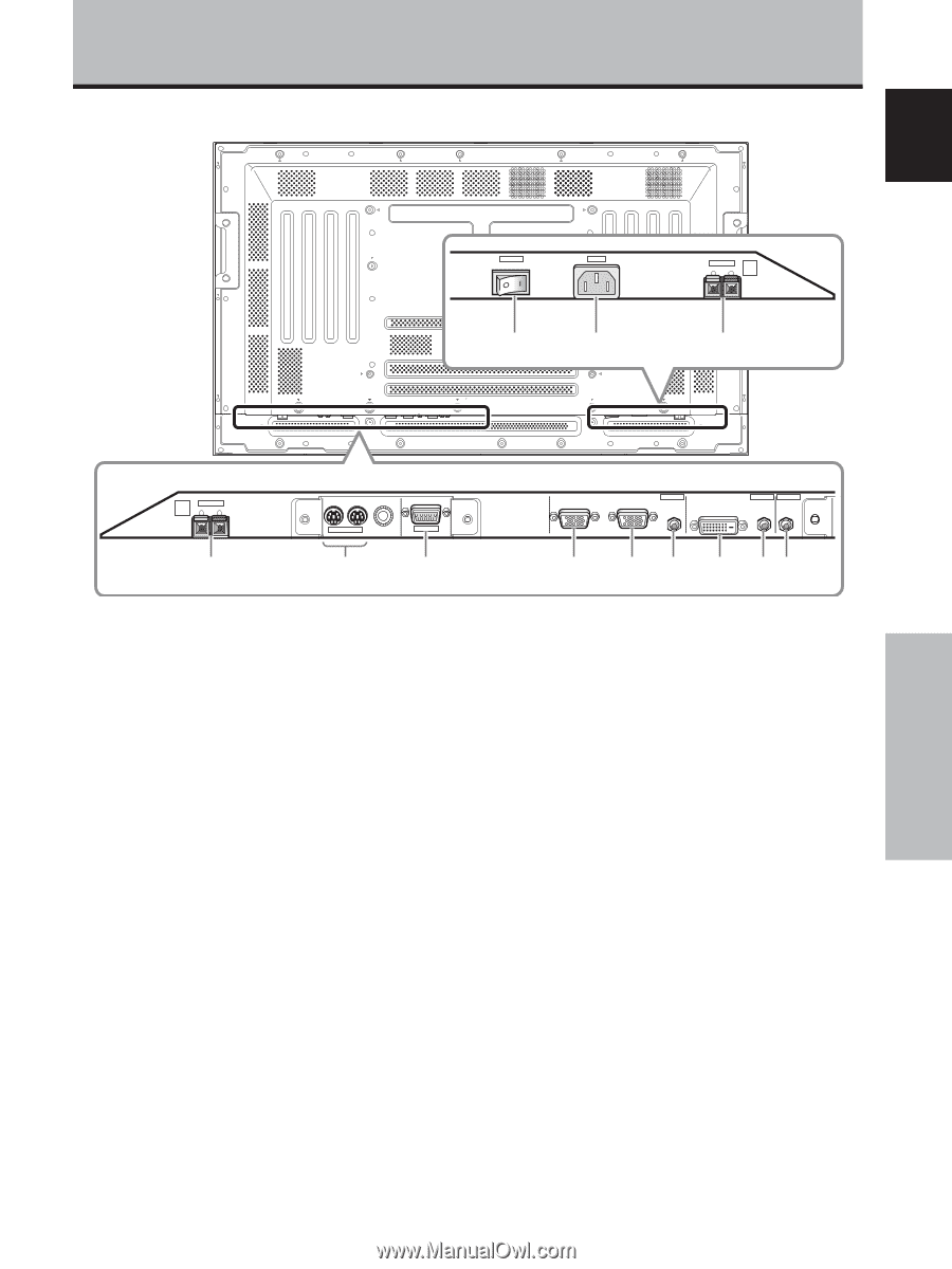
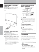
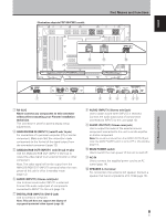
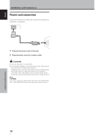
English Illustration depicts PDP-504CMX model. Part Names and Functions POWER OFF ON AC IN 0 - SPEAKER 8+Ω ~16Ω- L = Part Names and Functions R SPEAKER 8+Ω ~16Ω- 1 IN OUT COMBINATION 2 RS-232C 3 ANALOG RGB IN D-Sub ANALOG RGB OUT D-Sub INPUT1 AUDIO DIGITAL RGB DVI-D INPUT2 OUTPUT AUDIO AUDIO 4 5 6 7 89 3 RS-232C Never connect any component to this connector without first consulting your Pioneer installation technician. This connector is used for plasma display setup adjustments. 4 ANALOG RGB IN (INPUT1) (mini D-sub 15 pin) For connection of a personal computer (PC) or similar component. Make sure that the connection made corresponds to the format of the signal output from the connected component (page 12). 5 ANALOG RGB OUT (INPUT1) (mini D-sub 15 pin) Use the ANALOG RGB OUT (INPUT1) terminal to output the video signal to an external monitor or other component. Note: The video signal will not be output from the ANALOG RGB OUT (INPUT1) terminal when the main power of this unit is off or in standby mode. (page 12) 6 AUDIO (INPUT1) (Stereo mini jack) Use to obtain sound when INPUT1 is selected. Connect the audio output jack of components connected to INPUT1 to this unit (page 13). 7 DIGITAL RGB (INPUT2) (DVI-D jack) Use to connect a computer. Note: This unit does not support the display of copyguard-protected video signals (page 12). 8 AUDIO (INPUT2) (Stereo mini jack) Use to obtain sound when INPUT2 is selected. Connect the audio output jack of components connected to INPUT2 to this unit (page 13). 9 AUDIO (OUTPUT) (Stereo mini jack) Use to output the audio of the selected source component connected to this unit to an AV amplifier or similar component. Note: No sound is produced from the AUDIO (OUTPUT) jack when the MAIN POWER switch is set to OFF or ON (standby) (page 13). 0 MAIN POWER switch Use to switch the main power of the unit on and off. - AC IN Use to connect the supplied power cord to an AC outlet (page 14). = SPEAKER (L) terminal For connection of an external left speaker. Connect a speaker that has an impedance of 8 -16 Ω (page 13). 9 En
-
 1
1 -
2
-
3
-
4
-
5
-
6
-
7
-
8
-
9
-
 10
10 -
 11
11 -
 12
12 -
 13
13 -
 14
14 -
 15
15 -
 16
16 -
 17
17 -
 18
18 -
 19
19 -
 20
20 -
21
-
22
-
23
-
24
-
25
-
26
-
27
-
28
-
29
-
30
-
31
-
32
-
33
-
34
-
35
-
36
-
37
-
38
-
39
-
40
-
41
-
42
-
43
-
44
-
45
-
46
-
47
-
48
-
49
-
50
-
51
-
52
-
53
-
54
-
55
-
56
-
57
-
58
-
59
-
60
-
61
-
62
-
63
-
64
-
65
-
66
-
67
-
68
-
69
-
70
-
71
-
72
-
73
-
74
-
75
-
76
-
77
-
78
-
79
-
80
-
81
-
82
-
83
-
84
-
85
-
86
-
87
-
88
-
89
-
90
-
91
-
92
-
93
-
94
-
95
 |
 |