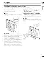
Pioneer PDP-5000EX User Manual - Page 15
SPEAKER R, Terminal for Service Adjustments, CONTROL IN/OUT, INPUT1, INPUT2, INPUT3, INPUT4, INPUT5
 |
View all Pioneer PDP-5000EX manuals
Add to My Manuals
Save this manual to your list of manuals |
Page 15 highlights
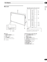
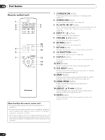
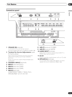
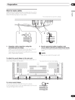
Part Names Connection panel R SPEAKER 8+Ω ~16Ω- 1 SERVICE ONLY CONTROL IN OUT 2 3 INPUT1 DVI-D INPUT2 HDMI INPUT3 HDMI 4 56 INPUT4 COMPONENT VIDEO / ANAROG RGB Y Pb/Cb Pr/Cr G B R HD VD INPUT5 S-VIDEO INPUT6 VIDEO AUDIO INPUT1 R L INPUT2 R L INPUT3 R L INPUT4 R L INPUT5 R L INPUT6 R L 7 89 10 English 05 AC IN SPEAKER 8Ω ~16Ω + - L 1 SPEAKER (R) terminals For connection of an external right speaker. Connect a speaker that has an impedance of 8 Ω to16 Ω. 2 Terminal for Service Adjustments (used for factory setup) Never connect any component to these connectors without first consulting your Pioneer installation technician. These connectors are used for Plasma Display setup adjustments. 3 CONTROL IN/OUT terminals 4 INPUT1 terminal (DVI-D) 5 INPUT2 terminal (HDMI) 6 INPUT3 terminal (HDMI) 7 INPUT4 terminals (COMPONENT VIDEO: Y, Pb/Cb, Pr/Cr, ANALOG RGB : G, B, R ,HD, VD) 11 12 8 INPUT5 terminal (S-VIDEO) 9 INPUT6 terminal (VIDEO) 10 AUDIO INPUT terminals Audio input connectors corresponding to INPUT1 to INPUT6 video input connectors. 11 AC IN Use to connect the supplied power cord to an AC outlet. 12 SPEAKER (L) terminals For connection of an external left speaker. Connect a speaker that has an impedance of 8 Ω to 16 Ω. 15 En
-
 1
1 -
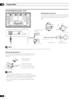
2
-
3
-
4
-
5
-
6
-
7
-
8
-
9
-
 10
10 -
 11
11 -
 12
12 -
 13
13 -
 14
14 -
 15
15 -
 16
16 -
 17
17 -
 18
18 -
 19
19 -
 20
20 -
21
-
22
-
23
-
24
-
25
-
26
-
27
-
28
-
29
-
30
-
31
-
32
-
33
-
34
-
35
-
36
-
37
-
38
-
39
-
40
-
41
-
42
-
43
-
44
-
45
-
46
-
47
-
48
-
49
-
50
-
51
-
52
-
53
-
54
-
55
-
56
-
57
-
58
-
59
-
60
-
61
-
62
-
63
-
64
-
65
-
66
-
67
-
68
-
69
-
70
-
71
-
72
-
73
-
74
-
75
-
76
-
77
-
78
-
79
-
80
-
81
-
82
-
83
-
84
-
85
-
86
-
87
-
88
-
89
-
90
-
91
-
92
-
93
-
94
-
95
-
96
-
97
-
98
-
99
-
100
-
101
-
102
-
103
-
104
-
105
-
106
-
107
-
108
-
109
-
110
-
111
-
112
-
113
-
114
-
115
-
116
-
117
-
118
-
119
-
120
-
121
-
122
-
123
-
124
-
125
-
126
-
127
-
128
-
129
-
130
-
131
-
132
-
133
-
134
-
135
-
136
-
137
-
138
-
139
-
140
-
141
-
142
-
143
-
144
-
145
-
146
-
147
-
148
-
149
-
150
-
151
-
152
-
153
-
154
-
155
-
156
-
157
-
158
-
159
-
160
-
161
-
162
-
163
-
164
-
165
-
166
-
167
-
168
-
169
-
170
-
171
-
172
-
173
-
174
-
175
-
176
-
177
-
178
-
179
-
180
-
181
-
182
-
183
-
184
-
185
-
186
-
187
-
188
-
189
-
190
-
191
-
192
-
193
-
194
-
195
-
196
-
197
-
198
-
199
-
200
-
201
-
202
-
203
-
204
-
205
-
206
-
207
-
208
-
209
-
210
-
211
-
212
-
213
-
214
-
215
-
216
-
217
-
218
-
219
-
220
-
221
-
222
-
223
-
224
-
225
-
226
-
227
-
228
-
229
-
230
 |
 |
