Sanyo 26KHHS72R Service Manual
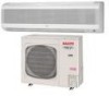
Sanyo 26KHHS72R - 23,000 BTU Ductless Single Zone Mini-Split Wall-Mounted Heat Pump Manual
 |
View all Sanyo 26KHHS72R manuals
Add to My Manuals
Save this manual to your list of manuals |
Sanyo 26KHHS72R manual content summary:
- Sanyo 26KHHS72R | Service Manual - Page 1
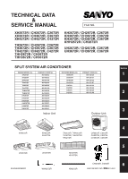
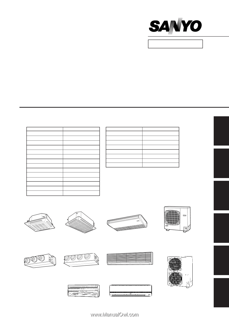
TECHNICAL DATA & SERVICE MANUAL FILE NO. XH2672R / CH2672R, C2672R XH3672R / CH3672R, C3672R XH4272R / CH4272R, C4272R TH2672R / UH2672R / CH2672R, C2672R UH3672R / CH3672R, C3672R SPLIT SYSTEM AIR CONDITIONER INDOOR MODEL No. XH2672R XH3672R XH4272R TH2672R TH3672R TH4272R THH2672R THH3672R - Sanyo 26KHHS72R | Service Manual - Page 2
- Sanyo 26KHHS72R | Service Manual - Page 3
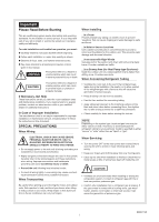
help for a special problem, contact our sales/service outlet or your certified dealer for additional instructions. In Case of Improper your back. Sharp edges or thin aluminum fins on the air conditioner can cut your fingers. W.....h..e...n....I.n...s...t.a..l..l.i.n...g ...In a Room Properly - Sanyo 26KHHS72R | Service Manual - Page 4
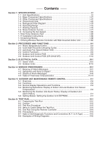
Refrigerant Flow Diagram I-74 1-6 Operating Range I-75 1-7 Heating Capacity I-76 1-8 Noise Criterion Curves I-77 1-9 Increasing the Fan Speed I-82 1-10 Air throw distance chart I-83 1-11 Installation Instructions Outdoor Units III-16 Section 4: SERVICE PROCEDURES IV-1 4-1 Meaning of Alarm - Sanyo 26KHHS72R | Service Manual - Page 5
I-47 1-4 Dimensional data ...I-63 1-5 Refrigerant Flow Diagram I-74 1-6 Operating Range ...I-75 1-7 Heating Capacity ...I-76 1-8 Noise Criterion Curves I-77 1-9 Increasing the Fan Speed I-82 1-10 Air throw distance chart I-83 1-11 Installation Instructions I-86 1-12 Electrical Wiring ...I-98 - Sanyo 26KHHS72R | Service Manual - Page 6
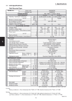
RCS-SH1UA / RCS-BH80UA. WL Air deflection (Horizontal / Vertical ) / Automatic (Vertical ) Air filter Washable Drain pump (Drain connection) 2 Compressor Operation sound Indoor - Hi/Me/Lo dB - A (20A , OD26mm) Rotary(SANYO) 45 / 42 / 40 Refrigerant control Outdoor - Hi dB - A 49 - Sanyo 26KHHS72R | Service Manual - Page 7
RCS-SH1UA / RCS-BH80UA. WL Air deflection (Horizontal / Vertical ) / Automatic (Vertical ) Air filter Washable Drain pump (Drain connection) Compressor (20A , OD26mm) Rotary(SANYO) 2 Operation sound Indoor - Hi/Me/Lo dB - A 48 / 42 / 38 Refrigerant control Outdoor - Hi dB - A 49 - Sanyo 26KHHS72R | Service Manual - Page 8
BH80UA. WL Air deflection (Horizontal / Vertical ) / Automatic (Vertical ) Air filter Washable Drain pump (Drain connection) 2 Compressor Operation sound Indoor - Hi/Me/Lo dB - A (20A , OD26mm) Rotary(SANYO) 46 / 42 / 38 Outdoor - Hi dB - A 52 Refrigerant control Electronic Expansion - Sanyo 26KHHS72R | Service Manual - Page 9
) / Automatic (Vertical ) Air filter Washable Drain pump (Drain connection) Compressor (20A , OD26mm) Rotary(SANYO) 2 Operation sound Indoor - Hi/Me/Lo dB - A 48 / 44 / 40 Outdoor - Hi dB - A 52 Refrigerant control Electronic Expansion Valve (MOV) REFRIGERANT TUBING Limit of tubing - Sanyo 26KHHS72R | Service Manual - Page 10
BH80UA. WL Air deflection (Horizontal / Vertical ) / Automatic (Vertical ) Air filter Washable Drain pump (Drain connection) 2 Compressor Operation sound Indoor - Hi/Me/Lo dB - A (20A , OD26mm) Rotary(SANYO) 48 / 42 / 38 Outdoor - Hi dB - A 49 Refrigerant control Electronic Expansion - Sanyo 26KHHS72R | Service Manual - Page 11
) / Automatic (Vertical ) Air filter Washable Drain pump (Drain connection) Compressor (20A , OD26mm) Rotary(SANYO) 2 Operation sound Indoor - Hi/Me/Lo dB - A 46 / 42 / 38 Outdoor - Hi dB - A 52 Refrigerant control Electronic Expansion Valve (MOV) REFRIGERANT TUBING Limit of tubing - Sanyo 26KHHS72R | Service Manual - Page 12
BH80UA. WL Air deflection (Horizontal / Vertical ) / Automatic (Vertical ) Air filter Washable Drain pump (Drain connection) 2 Compressor Operation sound Indoor - Hi/Me/Lo dB - A (20A , OD26mm) Rotary(SANYO) 48 / 44 / 40 Outdoor - Hi dB - A 52 Refrigerant control Electronic Expansion - Sanyo 26KHHS72R | Service Manual - Page 13
(Vertical ) Air filter Washable, long life (2,500 hr) Drain pump (Drain connection) Compressor Operation sound Indoor - Hi/Me/Lo Max.head 2-33/64 in. above drain connection (25A , OD32mm) Rotary(SANYO) 2 dB - A 38 / 35 / 31 Outdoor - Hi dB - A 49 Refrigerant control Electronic - Sanyo 26KHHS72R | Service Manual - Page 14
(Vertical ) Air filter Washable, long life (2,500 hr) Drain pump (Drain connection) 2 Compressor Max.head 2-33/64 in. above drain connection (25A , OD32mm) Rotary(SANYO) Operation sound Indoor - Hi/Me/Lo dB - A 44 / 37 / 33 Outdoor - Hi dB - A 52 Refrigerant control Electronic - Sanyo 26KHHS72R | Service Manual - Page 15
(Vertical ) Air filter Washable, long life (2,500 hr) Drain pump (Drain connection) Compressor Operation sound Indoor - Hi/Me/Lo Max.head 2-33/64 in. above drain connection (25A , OD32mm) Rotary(SANYO) 2 dB - A 45 / 38 / 34 Outdoor - Hi dB - A 53 Refrigerant control Electronic - Sanyo 26KHHS72R | Service Manual - Page 16
(Vertical ) Air filter Washable, long life (2,500 hr) Drain pump (Drain connection) 2 Compressor Max.head 2-33/64 in. above drain connection (25A , OD32mm) Rotary(SANYO) Operation sound Indoor - Hi/Me/Lo dB - A 38 / 35 / 31 Outdoor - Hi dB - A 49 Refrigerant control Electronic - Sanyo 26KHHS72R | Service Manual - Page 17
(Vertical ) Air filter Washable, long life (2,500 hr) Drain pump (Drain connection) Compressor Operation sound Indoor - Hi/Me/Lo Max.head 2-33/64 in. above drain connection (25A , OD32mm) Rotary(SANYO) 2 dB - A 44 / 37 / 33 Outdoor - Hi dB - A 52 Refrigerant control Electronic - Sanyo 26KHHS72R | Service Manual - Page 18
(Vertical ) Air filter Washable, long life (2,500 hr) Drain pump (Drain connection) 2 Compressor Max.head 2-33/64 in. above drain connection (25A , OD32mm) Rotary(SANYO) Operation sound Indoor - Hi/Me/Lo dB - A 45 / 38 / 34 Outdoor - Hi dB - A 53 Refrigerant control Electronic - Sanyo 26KHHS72R | Service Manual - Page 19
. WL Air deflection (Horizontal / Vertical ) Air filter Drain pump (Drain connection) Compressor Operation sound Indoor - Hi/Me/Lo Max.head 2-33/64 in. above drain connection (25A , OD32mm) Rotary(SANYO) 2 dB - A 34 / 30 / 27 Outdoor - Hi dB - A 49 Refrigerant control Electronic - Sanyo 26KHHS72R | Service Manual - Page 20
BH80UA. WL Air deflection (Horizontal / Vertical ) Air filter Drain pump (Drain connection) 2 Compressor Max.head 2-33/64 in. above drain connection (25A , OD32mm) Rotary(SANYO) Operation sound Indoor - Hi/Me/Lo dB - A 38 / 33 / 31 Outdoor - Hi dB - A 52 Refrigerant control Electronic - Sanyo 26KHHS72R | Service Manual - Page 21
WL Air deflection (Horizontal / Vertical ) - Air filter - Drain pump (Drain connection) Compressor Operation sound Indoor - Hi/Me/Lo Max.head 2-33/64 in. above drain connection (25A , OD32mm) Rotary(SANYO) 2 dB - A 34 / 30 / 27 Outdoor - Hi dB - A 49 Refrigerant control Electronic - Sanyo 26KHHS72R | Service Manual - Page 22
. WL Air deflection (Horizontal / Vertical ) - Air filter - Drain pump (Drain connection) 2 Compressor Max.head 2-33/64 in. above drain connection (25A , OD32mm) Rotary(SANYO) Operation sound Indoor - Hi/Me/Lo dB - A 38 / 33 / 31 Outdoor - Hi dB - A 52 Refrigerant control Electronic - Sanyo 26KHHS72R | Service Manual - Page 23
(Vertical ) Air filter Washable, long life (2,500 hr) Drain pump (Drain connection) Compressor (20A , OD26mm) Rotary(SANYO) 2 Operation sound Indoor - Hi/Me/Lo dB - A 39 / 37 / 33 Outdoor - Hi dB - A 49 Refrigerant control Electronic Expansion Valve (MOV) REFRIGERANT TUBING Limit - Sanyo 26KHHS72R | Service Manual - Page 24
(Horizontal / Vertical ) / Automatic (Vertical ) Air filter Drain pump (Drain connection) 2 Compressor Operation sound Indoor - Hi/Me/Lo dB - A Washable, long life (2,500 hr) (20A , OD26mm) Rotary(SANYO) 39 / 37 / 33 Outdoor - Hi dB - A 49 Refrigerant control Electronic Expansion Valve - Sanyo 26KHHS72R | Service Manual - Page 25
(Vertical ) Air filter Washable, long life (2,500 hr) Drain pump (Drain connection) Compressor (20A , OD26mm) Rotary(SANYO) 2 Operation sound Indoor - Hi/Me/Lo dB - A 42 / 40 / 35 Outdoor - Hi dB - A 52 Refrigerant control Electronic Expansion Valve (MOV) REFRIGERANT TUBING Limit - Sanyo 26KHHS72R | Service Manual - Page 26
(Horizontal / Vertical ) / Automatic (Vertical ) Air filter Drain pump (Drain connection) 2 Compressor Operation sound Indoor - Hi/Me/Lo dB - A Washable, long life (2,500 hr) (20A , OD26mm) Rotary(SANYO) 42 / 40 / 35 Outdoor - Hi dB - A 52 Refrigerant control Electronic Expansion Valve - Sanyo 26KHHS72R | Service Manual - Page 27
(Vertical ) Air filter Washable, long life (2,500 hr) Drain pump (Drain connection) Compressor (20A , OD26mm) Rotary(SANYO) 2 Operation sound Indoor - Hi/Me/Lo dB - A 44 / 41 / 37 Outdoor - Hi dB - A 53 Refrigerant control Electronic Expansion Valve (MOV) REFRIGERANT TUBING Limit - Sanyo 26KHHS72R | Service Manual - Page 28
(Horizontal / Vertical ) / Automatic (Vertical ) Air filter Drain pump (Drain connection) 2 Compressor Operation sound Indoor - Hi/Me/Lo dB - A Washable, long life (2,500 hr) (20A , OD26mm) Rotary(SANYO) 39 / 37 / 33 Outdoor - Hi dB - A 49 Refrigerant control Electronic Expansion Valve - Sanyo 26KHHS72R | Service Manual - Page 29
(Vertical ) Air filter Washable, long life (2,500 hr) Drain pump (Drain connection) Compressor (20A , OD26mm) Rotary(SANYO) 2 Operation sound Indoor - Hi/Me/Lo dB - A 42 / 40 / 35 Outdoor - Hi dB - A 52 Refrigerant control Electronic Expansion Valve (MOV) REFRIGERANT TUBING Limit - Sanyo 26KHHS72R | Service Manual - Page 30
(Horizontal / Vertical ) / Automatic (Vertical ) Air filter Drain pump (Drain connection) 2 Compressor Operation sound Indoor - Hi/Me/Lo dB - A Washable, long life (2,500 hr) (20A , OD26mm) Rotary(SANYO) 44 / 41 / 37 Outdoor - Hi dB - A 53 Refrigerant control Electronic Expansion Valve - Sanyo 26KHHS72R | Service Manual - Page 31
1-2 Major Component Specifications 1. Specifications (A) Indoor Unit MODEL No. XH2672R Source 230 - 208 VAC / 1 phase / 60 Hz Remote controller (Option) Wired or Wireless (See Unit Specification) Controller P. C. B Ass'y CR - TH2672 Control circuit fuse 250 VAC, 5 A Fan (Number ... - Sanyo 26KHHS72R | Service Manual - Page 32
1-2 Major Component Specifications 1. Specifications (A) Indoor Unit MODEL No. XH3672R Source 230 - 208 VAC / 1 phase / 60 Hz Remote controller (Option) Wired or Wireless (See Unit Specification) Controller P. C. B Ass'y CR - TH2672 Control circuit fuse 250 VAC, 5 A Fan (Number ... - Sanyo 26KHHS72R | Service Manual - Page 33
1-2 Major Component Specifications 1. Specifications (A) Indoor Unit MODEL No. XH4272R Source 230 - 208 VAC / 1 phase / 60 Hz Remote controller (Option) Wired or Wireless (See Unit Specification) Controller P. C. B Ass'y CR - TH2672 Control circuit fuse 250 VAC, 5 A Fan (Number ... - Sanyo 26KHHS72R | Service Manual - Page 34
1-2 Major Component Specifications 1. Specifications (A) Indoor Unit MODEL No. TH2672R Source 230 - 208 V / 1 phase / 60 Hz Remote controller (Option) Wired or Wireless (See Unit Specification) Controller P. C. B Ass'y CR - TH2672 Control circuit fuse 250 V, 5 A Fan (Number ... diameter - Sanyo 26KHHS72R | Service Manual - Page 35
1-2 Major Component Specifications 1. Specifications (A) Indoor Unit MODEL No. TH3672R Source 230 - 208 V / 1 phase / 60 Hz Remote controller (Option) Wired or Wireless (See Unit Specification) Controller P. C. B Ass'y CR - TH2672 Control circuit fuse 250 V, 5 A Fan (Number ... diameter - Sanyo 26KHHS72R | Service Manual - Page 36
1-2 Major Component Specifications 1. Specifications (A) Indoor Unit MODEL No. TH4272R Source 230 - 208 V / 1 phase / 60 Hz Remote controller (Option) Wired or Wireless (See Unit Specification) Controller P. C. B Ass'y CR - TH2672 Control circuit fuse 250 V, 5 A Fan (Number ... diameter - Sanyo 26KHHS72R | Service Manual - Page 37
1-2 Major Component Specifications 1. Specifications (A) Indoor Unit MODEL No. THH2672R Source 230 - 208 V / 1 phase / 60 Hz Remote controller (Option) Wired or Wireless (See Unit Specification) Controller P. C. B Ass'y CR - TH2672 Control circuit fuse 250 V, 5 A Fan (Number ... - Sanyo 26KHHS72R | Service Manual - Page 38
1-2 Major Component Specifications 1. Specifications (A) Indoor Unit MODEL No. THH3672R Source 230 - 208 V / 1 phase / 60 Hz Remote controller (Option) Wired or Wireless (See Unit Specification) Controller P. C. B Ass'y CR - TH2672 Control circuit fuse 250 V, 5 A Fan (Number ... - Sanyo 26KHHS72R | Service Manual - Page 39
1-2 Major Component Specifications 1. Specifications (A) Indoor Unit MODEL No. UH2672R Source 230 - 208 V / 1 phase / 60 Hz Remote controller (Option) Wired or Wireless (See Unit Specification) Controller P. C. B Ass'y CR - TH2672 Control circuit fuse 250 V, 5 A Fan (Number ... diameter - Sanyo 26KHHS72R | Service Manual - Page 40
1-2 Major Component Specifications 1. Specifications (A) Indoor Unit MODEL No. Source Remote controller (Option) Controller P. C. B Ass'y Control circuit fuse Fan (Number ... diameter) Fan motor Model Source No. of pole ... r.p.m. (230 V, High) Nominal output Coil resistance (Ambient temperature - Sanyo 26KHHS72R | Service Manual - Page 41
1-2 Major Component Specifications 1. Specifications (A) Indoor Unit MODEL No. KH2672R Source 230 - 208 V / 1 phase / 60 Hz Remote controller (Option) Wired or Wireless (See Unit Specification) Controller P. C. B Ass'y CB - KR24GXH56A Control circuit fuse 250 V, 5 A Fan Cross-flow - Sanyo 26KHHS72R | Service Manual - Page 42
1-2 Major Component Specifications 1. Specifications (A) Indoor Unit MODEL No. KH3072R Source 230 - 208 V / 1 phase / 60 Hz Remote controller (Option) Wired or Wireless (See Unit Specification) Controller P. C. B Ass'y CR - TH2672 Control circuit fuse 250 V, 5 A Fan Cross-flow Number - Sanyo 26KHHS72R | Service Manual - Page 43
1-2 Major Component Specifications 1. Specifications (A) Indoor Unit MODEL No. KH3672R Source 230 - 208 V / 1 phase / 60 Hz Remote controller (Option) Wired or Wireless (See Unit Specification) Controller P. C. B Ass'y CR - TH2672 Control circuit fuse 250 V, 5 A Fan Cross-flow Number - Sanyo 26KHHS72R | Service Manual - Page 44
1-2 Major Component Specifications 1. Specifications (A) Indoor Unit MODEL No. KHH2672R Source 230 - 208 V / 1 phase / 60 Hz Remote controller (Option) Wired or Wireless (See Unit Specification) Controller P. C. B Ass'y CR - TH2672 Control circuit fuse 250 V, 5 A Fan Cross-flow Number - Sanyo 26KHHS72R | Service Manual - Page 45
temperature 25 °C) Safety control Microprocessor safety devices Overload protector (Operating temperature) Crank case heater Refrigerant amount at shipment High pressure switch Set pressure Fan Number.. diameter Air circulation (Hi) Fan speeds (Max.) Fan motor Model No. Source No. of pole Nominal - Sanyo 26KHHS72R | Service Manual - Page 46
25 °C) Safety control Microprocessor safety devices Overload protector (Operating temperature) Crank case heater Refrigerant amount at shipment High pressure switch 1 Set pressure Fan Number.. diameter 2 Air circulation (Hi) Fan speeds (Max.) Fan motor Model No. Source No. of pole - Sanyo 26KHHS72R | Service Manual - Page 47
temperature 25 °C) Safety control Microprocessor safety devices Overload protector (Operating temperature) Crank case heater Refrigerant amount at shipment High pressure switch Set pressure Fan Number.. diameter Air circulation (Hi) Fan speeds (Max.) Fan motor Model No. Source No. of pole Nominal - Sanyo 26KHHS72R | Service Manual - Page 48
25 °C) Safety control Microprocessor safety devices Overload protector (Operating temperature) Crank case heater Refrigerant amount at shipment High pressure switch 1 Set pressure Fan Number.. diameter 2 Air circulation (Hi) Fan speeds (Max.) Fan motor Model No. Source No. of pole - Sanyo 26KHHS72R | Service Manual - Page 49
temperature 25 °C) Safety control Microprocessor safety devices Overload protector (Operating temperature) Crank case heater Refrigerant amount at shipment High pressure switch Set pressure Fan Number.. diameter Air circulation (Hi) Fan speeds (Max.) Fan motor Model No. Source No. of pole Nominal - Sanyo 26KHHS72R | Service Manual - Page 50
25 °C) Safety control Microprocessor safety devices Overload protector (Operating temperature) Crank case heater Refrigerant amount at shipment High pressure switch 1 Set pressure Fan Number.. diameter 2 Air circulation (Hi) Fan speeds (Max.) Fan motor Model No. Source No. of pole - Sanyo 26KHHS72R | Service Manual - Page 51
1-3 Other Component Specifications 1. Specifications (A) Indoor Unit MODEL No. XH2672R Power Transformer ATR - IIK224A Rated Primary 220 VAC, 60 Hz Secondary BRN - BRN : 14 V, 0.45 A, RED - RED : 14 V, 0.3 A Capacity - Coil resistance Ω (Ambient temprature 77 °F) WHT - WHT : 61.0 , - Sanyo 26KHHS72R | Service Manual - Page 52
1-3 Other Component Specifications 1. Specifications (A) Indoor Unit MODEL No. Power Transformer Rated Primary Secondary Capacity Coil resistance (Ambient temprature 77 °F) Ω Thermistor cut off temperature °F Thermistor (Coil sensor) : TH2, 3 Coil resistance kΩ Thermistor (Room - Sanyo 26KHHS72R | Service Manual - Page 53
1-3 Other Component Specifications 1. Specifications (A) Indoor Unit MODEL No. Power Transformer Rated Primary Secondary Capacity Coil resistance (Ambient temprature 77 °F) Ω Thermistor cut off temperature °F Thermistor (Coil sensor) : TH2, 3 Coil resistance kΩ Thermistor (Room - Sanyo 26KHHS72R | Service Manual - Page 54
1-3 Other Component Specifications 1. Specifications (A) Indoor Unit MODEL No. Power Transformer Rated Primary Secondary Capacity Coil resistance (Ambient temprature 77 °F) Ω Thermistor cut off temperature °F Thermistor (Coil sensor) Coil resistance kΩ Thermistor (Room or coil sensor - Sanyo 26KHHS72R | Service Manual - Page 55
1-3 Other Component Specifications 1. Specifications (A) Indoor Unit MODEL No. Power Transformer Rated Primary Secondary Capacity Coil resistance Ω (Ambient temprature 77 °F) Thermistor cut off temperature °F Thermistor (Coil sensor) Coil resistance kΩ Thermistor (Room or coil - Sanyo 26KHHS72R | Service Manual - Page 56
1-3 Other Component Specifications 1. Specifications (A) Indoor Unit MODEL No. Power Transformer Rated Primary Secondary Capacity Coil resistance (Ambient temprature 77 °F) Ω Thermistor cut off temperature °F Thermistor (Coil sensor) Coil resistance kΩ Thermistor (Room or coil sensor - Sanyo 26KHHS72R | Service Manual - Page 57
1-3 Other Component Specifications 1. Specifications (A) Indoor Unit MODEL No. Power Transformer Rated Primary Secondary Capacity Coil resistance (Ambient temprature 77 °F) Ω Thermistor cut off temperature °F Thermistor (Coil sensor) Coil resistance kΩ Thermistor (Room or coil sensor - Sanyo 26KHHS72R | Service Manual - Page 58
1-3 Other Component Specifications 1. Specifications (A) Indoor Unit MODEL No. Power Transformer Rated Primary Secondary Capacity Coil resistance Ω (Ambient temprature 77 °F) Thermistor cut off temperature °F Thermistor (Coil sensor) Coil resistance kΩ Thermistor (Room or coil - Sanyo 26KHHS72R | Service Manual - Page 59
1-3 Other Component Specifications 1. Specifications (A) Indoor Unit MODEL No. Power Transformer Rated Primary Secondary Capacity Coil resistance (Ambient temprature 77 °F) Ω Thermistor cut off temperature °F Thermistor (Coil sensor) Coil resistance kΩ Thermistor (Room or coil sensor - Sanyo 26KHHS72R | Service Manual - Page 60
1-3 Other Component Specifications 1. Specifications (A) Indoor Unit MODEL No. Power Transformer Rated Primary Secondary Capacity Coil resistance (Ambient temprature 77 °F) Ω Thermistor cut off temperature °F Thermistor (Coil sensor) Coil resistance kΩ Thermistor (Room or coil sensor - Sanyo 26KHHS72R | Service Manual - Page 61
1-3 Other Component Specifications 1. Specifications (A) Indoor Unit MODEL No. Power Transformer Rated Primary Secondary Capacity Coil resistance Ω (Ambient temprature 77 °F) Thermistor cut off temperature °F Thermistor (Coil sensor) Coil resistance kΩ Thermistor (Room or coil - Sanyo 26KHHS72R | Service Manual - Page 62
1-3 Other Component Specifications 1. Specifications (A) Indoor Unit MODEL No. Power Transformer Rated Primary Secondary Capacity Coil resistance (Ambient temprature 77 °F) Ω Thermistor cut off temperature °F Thermistor (Coil sensor) Coil resistance kΩ Thermistor (Room or coil sensor - Sanyo 26KHHS72R | Service Manual - Page 63
1-3 Other Component Specifications 1. Specifications (A) Indoor Unit MODEL No. Power Transformer Rated Primary Secondary Capacity Coil resistance Ω (Ambient temprature 77 °F) Thermistor cut off temperature °F Thermistor (Coil sensor) Coil resistance kΩ Thermistor (Room or coil - Sanyo 26KHHS72R | Service Manual - Page 64
1-3 Other Component Specifications 1. Specifications (B) Outdoor Unit MODEL No. Thermistor (Coil sensor) : TH2 to 5 Coil resistance kΩ Thermistor (Comp. discharge gas sensor) : TH6 Coil resistance kΩ Solenoid coil or 4 way valve 4 way valve Solenoid coil Electric expansion valve (MOV) - Sanyo 26KHHS72R | Service Manual - Page 65
1-3 Other Component Specifications 1. Specifications (B) Outdoor Unit MODEL No. Thermistor (Coil sensor) : TH2 to 5 Coil resistance kΩ Thermistor (Comp. discharge gas sensor) : TH6 Coil resistance kΩ Solenoid coil or 4 way valve 4 way valve Solenoid coil Electric expansion valve (MOV) - Sanyo 26KHHS72R | Service Manual - Page 66
MODEL No. Thermistor (Coil sensor) : TH2 to 5 Coil resistance kΩ Thermistor (Comp. discharge gas sensor) : TH6 Coil resistance kΩ Solenoid coil or 4 way valve 4 way valve Solenoid coil Electric expansion valve (MOV) Valve Coil 1 1. Specifications CH4272R, C4272R 14 °F : 23.7 23 °F : 18.8 - Sanyo 26KHHS72R | Service Manual - Page 67
32 1 1 14-1/2 3-15/16 33-27/32 19-11/16 30-9/16 4-7/8 8-11/16 Dimension : inch Air intake grille Air outlet Refrigerant liquid line (3/8") Flare connection Refrigerant gas line (5/8") Flare connection Drain connection Power supply entry (conduit size : 1/2") For discharge duct Suspention bolt - Sanyo 26KHHS72R | Service Manual - Page 68
15/32 Detail of 9 2-5/32 4-ø1/8 hole 4-ø1/8 hole 4 2-3/8 30-9/16 7-3/32 9 Dimension : inch Air intake grille Air outlet Refrigerant liquid line (3/8") Flare connection Refrigerant gas line (5/8") Flare connection Drain connection 5 Power supply entry (conduit size : 1/2") For discharge - Sanyo 26KHHS72R | Service Manual - Page 69
7-15/32 10 10 9-7/8 Air outlet or more 51-3/16 or more 8-7/16 (Service space) Front (Service space) 9-7/8 2 Air intake 2 ft. or more 3-1/2 3 4-1/16 5-25/32 7-7/32 Dimension : inch 4 Drain connection Drain connection for left side Refrigerant liquid line (3/8") Flare connection - Sanyo 26KHHS72R | Service Manual - Page 70
26-3/8 10 9-7/8 Air outlet or more 2 (Service space) Air intake 62 Front 10 or more (Service space) 8-7/16 9-7/8 5-1/2 7-3/4 9-7/16 2 ft. or more 3 3-1/2 4-1/16 5-25/32 7-7/32 4 Dimension : inch Drain connection Drain connection for left side Refrigerant liquid line (3/8") Flare - Sanyo 26KHHS72R | Service Manual - Page 71
12/32 39-3/8 42-17/32 (Suspension bolt pitch) 35-7/16 37-7/8 (Air outlet duct flange) 11-13/32 1-7/32 3-17/32 3 22-27/32 (Suspension bolt pitch) 31/32 Dimension : inch 7-9/32 Refrigerant liquid line (3/8") Flare connection Refrigerant gas line (5/8") Flare connection 4 Upper drain port - Sanyo 26KHHS72R | Service Manual - Page 72
32 61-13/32 (Suspension bolt pitch) 56-25/32 (Air outlet duct flange) 9-1/16 P × 6 = 54-11/32 3 13-3/16 1-7/32 4 22-27/32 (Suspension bolt pitch) 31/32 Dimension : inch Refrigerant liquid line (3/8") Flare connection Refrigerant gas line (5/8") Flare connection 3-17/32 Upper drain port - Sanyo 26KHHS72R | Service Manual - Page 73
1-4 Dimensional data Indoor unit : Concealed Duct Type Flange for the air intake duct (Field supply) : For Concealed Duct Type Thickness more than T1/16 inch 1. Specifications 2-ø1/8 (Hole) 13/32 31/32 31/32 13/32 8-9/32 - Sanyo 26KHHS72R | Service Manual - Page 74
KHH2672R 1. Specifications 2-1/4 14-9/16 49-7/32 2-3/4 8-9/32 1 4-5/32 2 Indoor unit : Wall Mounted Type KH2672R 3 Refrigerant liquid line (3/8") Flare connection Refrigerant gas line (5/8") Flare connection Drain hose OD 1-1/4 Dimension : inch 1911_X_S 4 Drain and wiring port (3-5/32 - Sanyo 26KHHS72R | Service Manual - Page 75
data Indoor unit : Wall Mounted Type 30, 36 Type 59-1/16 1. Specifications 9-7/16 2-3/4 1-49/64 14-9/16 2-9/16 1 Refrigerant liquid line (3/8") Flare connection Refrigerant gas line (5/8") Flare connection Drain hose OD 1-1/4 Dimension : inch 1912_X_S 2 3 4 5 6 SM831148 I-71 - Sanyo 26KHHS72R | Service Manual - Page 76
1-4 Dimensional Data (B) Outdoor Unit: CH2672R, C2672R CH3072R, C3072R CH3672R, C3672R 1. Specifications 1 2 3 4 5 6 SM831148 I-72 - Sanyo 26KHHS72R | Service Manual - Page 77
1-4 Dimensional Data (B) Outdoor Unit: CH4272R, C4272R 1. Specifications 1 2 3 4 5 6 SM831148 I-73 - Sanyo 26KHHS72R | Service Manual - Page 78
1-5 Refrigerant Flow Diagram Outdoor Unit: CH2672R, C2672R CH3072R, C3072R CH3672R, C3672R 1. Specifications Indoor Unit: 26, 30, 36 Type 1 2 3 4 5 6 SM831148 I-74 - Sanyo 26KHHS72R | Service Manual - Page 79
1-5 Refrigerant Flow Diagram Outdoor Unit: CH4272R, C4272R Indoor Unit: 42 Type 1. Specifications 1-6 Operating Range Cooling Heating Temperature Maximum Minimum Maximum Minimum Indoor Air Intake 95 °F DB / 71 °F WB 67 °F DB / 57 °F WB 80 °F DB / 67 °F WB -DB / -WB Outdoor Air Intake 109 °F - Sanyo 26KHHS72R | Service Manual - Page 80
1-7 Heating Capacity CH2672R, C2672R CH3072R, C3072R CH3672R, C3672R CH4272R, C4272R 1. Specifications 1 2 3 4 5 6 SM831148 I-76 - Sanyo 26KHHS72R | Service Manual - Page 81
1-8 Noise Criterion Curves 4-Way Air Discharge Semi-concealed Type MODEL : XH2672R SOUND LEVEL : HIGH 38 dB(A), NC 31 LOW 31 dB(A), NC 23 CONDITION : Center, Under the unit 4.9 ft. SOURCE - Sanyo 26KHHS72R | Service Manual - Page 82
1-8 Noise Criterion Curves Ceiling Mounted Type MODEL : TH2672R, THH2672R SOUND LEVEL : HIGH 40 dB(A), NC 34 LOW 36 dB(A), NC 26 CONDITION : Distance 3.3 ft., Under the unit 3.3 ft. SOURCE 60 : 208 - 230 V, 1 Phase, 60 Hz 1. Specifications MODEL : TH3672R, THH3672R SOUND LEVEL : HIGH 46 - Sanyo 26KHHS72R | Service Manual - Page 83
1-8 Noise Criterion Curves Concealed Duct Type MODEL : UH2672R SOUND LEVEL : HIGH 34 dB(A), NC 22 / LOW 27 dB(A), NC 18 CONDITION : Under the unit 4.9 ft. SOURCE : 208 - 230 V, 1 Phase, 60 Hz 1. Specifications MODEL : UH3672R SOUND LEVEL : HIGH 38 dB(A), NC 30 / LOW 31 dB(A), NC 21 - Sanyo 26KHHS72R | Service Manual - Page 84
1-8 Noise Criterion Curves Wall Mounted Type 1. Specifications CONDITION SOURCE : Distance 3.3 ft., Under the unit 3.3 ft. : 208 - 230 V, 1 Phase, 60 Hz MODEL : KHH2672R SOUND LEVEL : HIGH 45 dB(A), NC 38 LOW 40 dB(A), NC 33 CONDITION : Distance 3.3 ft., Under the unit 3.3 ft. SOURCE 60 : - Sanyo 26KHHS72R | Service Manual - Page 85
1-8 Noise Criterion Curves Outdoor Units 1. Specifications 1 2 3 4 5 REMARKS: 1. Value obtained in the actual place where the unit is installed may be slightly higher than the values shown in this graph because of the conditions of operation, the structure of the building, the background noise - Sanyo 26KHHS72R | Service Manual - Page 86
1. Specifications If external static pressure is too great (due to long extension of ducts, for example), the air flow volume may drop too low at each air outlet. This problem may be solved by increasing the fan speed using the following procedure: (1) Remove 4 screws on the electrical component - Sanyo 26KHHS72R | Service Manual - Page 87
: 36, 42 Type HORIZONTAL DISTANCE (ft.) 03 7 10 13 17 20 0 3 AXIS AIR VELOCITY 7 10 13 2112_X_I 1. Specifications 1 2 3 : LOUVER ANGLE 20˚ in Cooling mode : LOUVER ANGLE 60˚ in Heating mode Condition Fan Speed : Hi 4 Room air temp. : 80˚F DB in cooling mode 68˚F DB in heating mode - Sanyo 26KHHS72R | Service Manual - Page 88
Model: 36 Type HORIZONTAL DISTANCE (ft.) 0 3 7 10 13 17 20 23 26 29 33 0 AXIS AIR VELOCITY (ft./sec) VERTICAL DISTANCE (ft.) 1 3 7 AXIS AIR VELOCITY 10 13 17 2 Model: 42 Type 2116_T_I AXIS AIR VELOCITY (ft./sec) VERTICAL DISTANCE (ft.) HORIZONTAL DISTANCE (ft.) 0 3 7 10 13 17 20 23 26 - Sanyo 26KHHS72R | Service Manual - Page 89
velocity (ft./sec.) Vertical distance (ft.) 45˚ 5 67.5˚ 10 0˚ 22.5˚ 45˚ 15 2121_K_S Model: KH2672R 0 Horizontal distance (ft.) Axis air velocity (ft./sec.) Vertical distance (ft.) 5 10 13 Model: KH3072R KH3672R 0 5 5 45˚ 67.5˚ 45˚ 10 13 Horizontal distance (ft.) 10 15 20 25 - Sanyo 26KHHS72R | Service Manual - Page 90
1-11 Installation Instructions Tubing Length Single type Refrigerant tubing between the indoor and outdoor units should be kept as short as possible. The length of the refrigerant tubes between the indoor and outdoor units are limited by the elevation difference between the 2 units. During tubing - Sanyo 26KHHS72R | Service Manual - Page 91
50 10 - 100 b) 0.43 6.2 No additional charge of compressor oil is necessary. *1 If total tubing length becomes 100 to 165 ft., charge additional refrigerant by 0.43 oz./ft. 1. Specifications C(H)4272R 3/8 (9.52) 5/8 (15.88) 165 100 50 10 - 100 b) 0.43 7.9 Table 1-3 List of Connection Tube Sizes - Sanyo 26KHHS72R | Service Manual - Page 92
a location where the ceiling is strong enough to support the weight of the unit. select a location where tubing and drain pipe have the shortest run to the outdoor unit. 3 allow room for operation and maintenance as well as unrestricted air flow around the unit. install the unit within the - Sanyo 26KHHS72R | Service Manual - Page 93
above unit) 1 Distance between obstructions and the unit air inlet and Air direction chamber outlet must be as shown below. (field level to reduce humidity and protect the unit gainst possible water damage and decreased service life. (Fig. 1-4) use lug bolts or equal to bolt down unit, - Sanyo 26KHHS72R | Service Manual - Page 94
wind In regions with snow and strong wind, the following problems may occur when the outdoor unit is not provided with a platform and snow-proof ducting: a) The outdoor fan may not run and damage to the unit may occur. b) There may be no air flow. Fig. 1-5 In regions with significant snowfall, the - Sanyo 26KHHS72R | Service Manual - Page 95
, remove the base of the chamber (10 screws) before using. 2 1 Unit front, air discharge chamber 2 Unit left side, air discharge chamber 3 Unit light side, air discharge chamber 2 4 Reinforcement brackets, 4 locations 1-1/8 9-7/16 1 3 4 11-13/16 3 9-7/16 1-1/8 1-3/8 1-3/8 9-27/32 - Sanyo 26KHHS72R | Service Manual - Page 96
Dimensions of Outdoor Unit with air-discharge chamber (field supply) For outdoor unit 2672R / 3072R / 3672R 6-11/16 25-31/32 4-5/16 1/2 Wind direction 1/2 25/32 13/32 14-31/32 - Sanyo 26KHHS72R | Service Manual - Page 97
discharge chamber (field supply) For outdoor unit C(H)2672R / 3072R / 3672R / 4272R Required space around outdoor unit 1. Specifications If the air discharge chamber is used, the space shown below must be secured around the outdoor unit. If the unit is used without the required space, a protective - Sanyo 26KHHS72R | Service Manual - Page 98
Dimensions of Snow Ducting Reference diagram for snow-proof vents (field supply) For outdoor unit 2672R / 3072R / 3672R 1 Unit top, snow-proof vent 2 Unit left side 3 Unit right side 4 Unit reverse side 5 Unit reverse side 6 Unit sides, reinforcement brackets for snow-proof vent 30-3/32 Fastened - Sanyo 26KHHS72R | Service Manual - Page 99
Dimensions of outdoor unit with snow-proof vents (field supply) 2672R / 3072R / 3672R unit with STK-BDRE80A 30-3/32 7-1/16 Wind direction Wind direction 1. Specifications 25/32 13/32 25-13/32 14-31/32 15-15/16 Wind direction Wind direction 37 3/4 19/32 11-29/32 16-3/4 30-23/32 Wind - Sanyo 26KHHS72R | Service Manual - Page 100
Reference diagram for snow-proof vents - 1 1. Specifications Space requirements for setting - (1) C(H)2672R / 3072R / 3672R / 4272R with STK-BDRE80A & STK-BDR140U [Obstacle to the rear of unit] [Obstacle to the front of unit] Top is open: (1) Single-unit installation (2) Obstacles on both sides - Sanyo 26KHHS72R | Service Manual - Page 101
Reference diagram for snow-proof vents - 2 Space requirements for setting - (2) C(H)2672R / 3072R / 3672R / 4272R with STK-BDRE80A & STK-BDR140U [Obstacles to the front and rear of unit] The top and both sides must remain open. Either the obstacle to the front or the obstacle to the rear must be no - Sanyo 26KHHS72R | Service Manual - Page 102
, the unit must be grounded. 8) To prevent malfunction of the air conditioner caused by electrical noise, care must be taken when wiring as follows of this appliance is dam- 5) Do not allow wiring to touch the refrigerant tubing, aged, it must be replaced by a repair shop appointed compressor, - Sanyo 26KHHS72R | Service Manual - Page 103
1. Specifications Indoor Unit Type (B) Power Supply AWG #14 Trade Size of Conduit MOP (Fuse or HACR type circuit breaker) X, K, T, U Max. length 67 ft. 3/4 in. 15 A Control Wiring (C) Inter-Unit Control Wiring AWG #18 Use high voltage wire (300 V)*1 (D) Remote Control Wiring AWG #18*2 (0.75 - Sanyo 26KHHS72R | Service Manual - Page 104
hazard may also exist. Therefore, ensure that all wiring is tightly connected. When connecting each power wire to the corresponding terminal, follow the instructions on "How to connect wiring to the terminal" and fasten the wire securely with the fixing screw of the terminal plate. Strip 3/8 in - Sanyo 26KHHS72R | Service Manual - Page 105
1. Specifications CAUTION (1) When linking outdoor units in a network (S-net link system), disconnect the terminal extended from the short plug (CN003, 2P Black, location: right bottom on the outdoor main control PCB) from all outdoor units except any one of the outdoor units. (When shipping: In - Sanyo 26KHHS72R | Service Manual - Page 106
1. Specifications 1-13 Using Wireless Remote Controller with Wall-mounted Indoor Unit When the wireless remote controller is to be used, slide the switch on the indoor unit control PCB. If this setting is not made, an alarm will occur.(The operation lamp on the display blinks.) This setting is not - Sanyo 26KHHS72R | Service Manual - Page 107
2. Processes and functions 2. PROCESSES AND FUNCTIONS 2-1 Room Temperature Control II-2 2-2 Cold Draft Prevention (Heating Cycle II-4 2-3 Automatic Fan Speed (Indoor Unit II-5 2-4 Control Functions ...II-6 2-5 Outdoor Unit Control PCB II-9 2-6 Outdoor Unit Control PCB (CR-CH4272R II-10 1 2 3 4 - Sanyo 26KHHS72R | Service Manual - Page 108
2. Processes and functions 2-1 Room Temperature Control The unit adjusts room temperature by turning the outdoor unit's compressor ON and OFF. This process is controlled by the thermostat located in the remote control unit. The figures on this and the next pages show how each part of the system - Sanyo 26KHHS72R | Service Manual - Page 109
2. Processes and functions (B) Heating REMOTE CONTROL SENSOR (Only for wireless remote controller) SET. +2 °F SETTING TEMP. SET. -2 °F THERMO. ON THERMO. ON THERMO. OFF THERMO. OFF THERMO. ON BODY SENSOR +2°F SET TEMP.+7 °F SHIFT -2°F THERMO. ON THERMO. OFF THERMO. ON THERMO. OFF THERMO. ON - Sanyo 26KHHS72R | Service Manual - Page 110
2. Processes and functions 2-2 Cold Draft Prevention (Heating Cycle) The cold draft prevention function controls indoor fan speed so a strong draft of cold air will not blow out before the indoor heat exchange coils have warmed up. ❑ STANDBY shows on the remote controller when the indoor fan speed - Sanyo 26KHHS72R | Service Manual - Page 111
2. Processes and functions 2-3 Automatic Fan Speed (Indoor Unit) By pressing the FAN SPEED button on the remote controller, the fan speed can be set at one of four steps: AUTO., HI., MED., or LO. When set at AUTO. the indoor unit fan speed will be automatically adjusted to the room temperature as - Sanyo 26KHHS72R | Service Manual - Page 112
unit fan minimum speed and maximum (2) If MAX (C1, C2) is 124°F or higher and less than speed are determined according to the outdoor air temperature and the operating frequency. The 142°F, the revolution of the compressor is controlled to prevent the high pressure being speed is controlled in - Sanyo 26KHHS72R | Service Manual - Page 113
-prohibit area), the compressor operating frequency is maintained. (3) If the temperature is in the "H" area (operating frequency control area), and the outdoor air temperature is less than 90°F, the compressor maximum operating frequency is limited according to the indoor unit fan speed. (4) If the - Sanyo 26KHHS72R | Service Manual - Page 114
fan: OFF 1 3 Start-up operation (1) Frost detection 1. Outdoor heat exchanger temperature (C1) method (15-minute mask after operation start) 2 3 4 2. Outdoor air temperature is 7°F or above and outdoor heat exchanger temperature (C1) of 0°F or below is detected continuously for 20 seconds - Sanyo 26KHHS72R | Service Manual - Page 115
(C1) sensor Heat exchanger temperature (C2) sensor Outdoor air temperature (TO) sensor Compressor discharge temperature (TD) sensor MDC EEPROM IC Power LED (D115) Refrigerant recovery switch (S005) Quiet mode plug (CN028) Refrigerant System address switch (S002) EXCT plug (CN026) Automatic - Sanyo 26KHHS72R | Service Manual - Page 116
recovery control using cooling operation. The indoor unit fan will operate at HIGH and 55 Hz for a maximum of 10 minutes. When refrigerant recovery is completed, close the valves and press this switch to stop the operation. 2P plug (red): Pin used for PCB inspection at the factory - Sanyo 26KHHS72R | Service Manual - Page 117
2. Processes and functions Terminal plug (CN015) Quiet mode (CN028) 3P plug (black): Terminal plug for the communications line • At the time of shipment from the factory, the short-circuiting socket (2P, black) is installed between pins 1 and 2 on the terminal plug (terminal = yes). • When central - Sanyo 26KHHS72R | Service Manual - Page 118
- Sanyo 26KHHS72R | Service Manual - Page 119
3. Electrical data 3. ELECTRICAL DATA 3-1 Indoor Units ...III-2 3-2 Outdoor Units ...III-16 1 2 3 4 5 6 SM831148 III-1 - Sanyo 26KHHS72R | Service Manual - Page 120
3-1 Indoor Units 3. Electrical data 4-Way Air Discharge Semi-concealed Type : XH2672R/XH3672R/XH4272R • Electric Wiring Diagram 1 2 3 4 5 6 SM831148 III-2 - Sanyo 26KHHS72R | Service Manual - Page 121
3. Electrical data 4-Way Air Discharge Semi-concealed Type : XH2672R/XH3672R/XH4272R • Schematic Diagram 1 2 3 4 5 6 SM831148 III-3 - Sanyo 26KHHS72R | Service Manual - Page 122
Ceiling Mounted Type : TH2672R/TH3672R/TH4272R 3. Electrical data • Electric Wiring Diagram 1 2 3 4 5 6 SM831148 III-4 - Sanyo 26KHHS72R | Service Manual - Page 123
Ceiling Mounted Type : TH2672R/TH3672R/TH4272R • Schematic Diagram 3. Electrical data 1 2 3 4 5 6 SM831148 III-5 - Sanyo 26KHHS72R | Service Manual - Page 124
Ceiling Mounted Type : THH2672R/THH3672R 3. Electrical data • Electric Wiring Diagram 1 2 3 4 5 6 SM831148 III-6 - Sanyo 26KHHS72R | Service Manual - Page 125
Ceiling Mounted Type : THH2672R/THH3672R • Schematic Diagram 3. Electrical data 1 2 3 4 5 6 SM831148 III-7 - Sanyo 26KHHS72R | Service Manual - Page 126
Concealed Duct Type : UH2672R/UH3672R 3. Electrical data • Electric Wiring Diagram 1 2 3 4 5 6 SM831148 III-8 - Sanyo 26KHHS72R | Service Manual - Page 127
Concealed Duct Type : UH2672R/UH3672R • Schematic Diagram 3. Electrical data 1 2 3 4 5 6 SM831148 III-9 - Sanyo 26KHHS72R | Service Manual - Page 128
Wall Mounted Type : KH2672R 3. Electrical data 1 2 3 4 5 6 III-10 SM831148 - Sanyo 26KHHS72R | Service Manual - Page 129
Wall Mounted Type : KH2672R • Schematic Diagram 3. Electrical data 1 2 3 4 5 III-11 6 SM831148 - Sanyo 26KHHS72R | Service Manual - Page 130
Wall Mounted Type : KH3072R/KH3672R 3. Electrical data • Electric Wiring Diagram 1 2 3 4 5 6 III-12 SM831148 - Sanyo 26KHHS72R | Service Manual - Page 131
Wall Mounted Type : KH3072R/KH3672R • Schematic Diagram 3. Electrical data 1 2 3 4 5 III-13 6 SM831148 - Sanyo 26KHHS72R | Service Manual - Page 132
Wall Mounted Type : KHH2672R 3. Electrical data • Electric Wiring Diagram 1 2 3 4 5 6 III-14 SM831148 - Sanyo 26KHHS72R | Service Manual - Page 133
Wall Mounted Type : KHH2672R • Schematic Diagram 3. Electrical data 1 2 3 4 5 III-15 6 SM831148 - Sanyo 26KHHS72R | Service Manual - Page 134
3-2 Outdoor Units CH2672R 3. Electrical data • Electric Wiring Diagram 1 2 3 4 5 6 III-16 SM831148 - Sanyo 26KHHS72R | Service Manual - Page 135
3-2 Outdoor Units CH2672R • Schematic Diagram 3. Electrical data 1 2 3 4 5 III-17 6 SM831148 - Sanyo 26KHHS72R | Service Manual - Page 136
3-2 Outdoor Units C2672R 3. Electrical data • Electric Wiring Diagram 1 2 3 4 5 6 III-18 SM831148 - Sanyo 26KHHS72R | Service Manual - Page 137
3-2 Outdoor Units C2672R • Schematic Diagram 3. Electrical data 1 2 3 4 5 III-19 6 SM831148 - Sanyo 26KHHS72R | Service Manual - Page 138
3-2 Outdoor Units CH3072R/CH3672R 3. Electrical data • Electric Wiring Diagram 1 2 3 4 5 6 III-20 SM831148 - Sanyo 26KHHS72R | Service Manual - Page 139
3-2 Outdoor Units CH3072R/CH3672R • Schematic Diagram 3. Electrical data 1 2 3 4 5 III-21 6 SM831148 - Sanyo 26KHHS72R | Service Manual - Page 140
3-2 Outdoor Units C3072R/C3672R 3. Electrical data • Electric Wiring Diagram 1 2 3 4 5 6 III-22 SM831148 - Sanyo 26KHHS72R | Service Manual - Page 141
3-2 Outdoor Units C3072R/C3672R • Schematic Diagram 3. Electrical data 1 2 3 4 5 III-23 6 SM831148 - Sanyo 26KHHS72R | Service Manual - Page 142
3-2 Outdoor Units CH4272R 3. Electrical data • Electric Wiring Diagram 1 2 3 4 5 6 III-24 SM831148 - Sanyo 26KHHS72R | Service Manual - Page 143
3-2 Outdoor Units CH4272R • Schematic Diagram 3. Electrical data 1 2 3 4 5 III-25 6 SM831148 - Sanyo 26KHHS72R | Service Manual - Page 144
3-2 Outdoor Units C4272R 3. Electrical data • Electric Wiring Diagram 1 2 3 4 5 6 III-26 SM831148 - Sanyo 26KHHS72R | Service Manual - Page 145
3-2 Outdoor Units C4272R • Schematic Diagram 3. Electrical data 1 2 3 4 5 III-27 6 SM831148 - Sanyo 26KHHS72R | Service Manual - Page 146
- Sanyo 26KHHS72R | Service Manual - Page 147
4. Service procedures 4. SERVICE PROCEDURES 4-1. Meaning of Alarm Messages IV-2 4-2. Symptoms and Parts to Inspect IV-5 4-3. Details of Alarm Messages IV-8 4-4. Table of Thermistor Characteristics IV-14 1 2 3 4 5 6 SM831148 IV-1 - Sanyo 26KHHS72R | Service Manual - Page 148
of remote controller switch alarm display Possible cause of malfunction 4. Service procedures ON: Blinking: OFF: Wired remote control display Wireless unit detected Error in transmitting serial communications signal E17 trouble in the signal from another indoor unit Error in receiving - Sanyo 26KHHS72R | Service Manual - Page 149
4. Service procedures Fan protective thermostat Float switch Discharge temperature trouble P01 P10 P03 Alternately Outdoor protection High temperature (C1) F04 F06 2 Outdoor heat exchanger temperature (C2) Outdoor air temperature (TO) F07 F08 Alter. Intake temperature (TS) F12 Indoor - Sanyo 26KHHS72R | Service Manual - Page 150
LED Indicator Messages on Outdoor Control PCB 4. Service procedures LED 1 LED 2 Remarks Power ON N = Alarm No. * Refer to "1. Examples of alarm display" below. Refrigerant recovery mode Automatic address setting Automatic address setting in progress Blinking alternately 2 Automatic address - Sanyo 26KHHS72R | Service Manual - Page 151
Service trouble 3. Check tubing sensor (TD). Recovery at restart 1. Check the high pressure switch connector is securely connected. 2. Check the ourdoor unit heat exchanger is not clogged (cooling operation). 3. Check the indoor unit air restart 1. Refrigerant cycle 3 protection trouble higher, - Sanyo 26KHHS72R | Service Manual - Page 152
trouble Compressor motor output trouble, Inverter compressor trouble, MDC trouble Inverter stops after alarm is detected. Recovery at restart 1. Refrigerant cycle trouble circuit Automatic recovery 1. Check outdoor air temp. circuit, or short circuit in outdoor air temp. sensor (TO) sensor ( - Sanyo 26KHHS72R | Service Manual - Page 153
4. Service procedures Remote controller alarm display Alarm contents F31 EEPROM trouble Judgment condition Reading/writing H01 Overcurrent Inverter stops after alarm is Recovery at restart 1. Refrigerant cycle trouble, detected. overload operation 2. Loose screws between HIC 5 control - Sanyo 26KHHS72R | Service Manual - Page 154
Compressor does not run. Breakdown Motor current detection circuit trouble No Is power OK? Correct power line. Yes Is current detection No circuit wiring OK? Check and correct wiring. 4. Service procedures Are wiring and connector No connections OK? Check and correct wiring. Yes - Sanyo 26KHHS72R | Service Manual - Page 155
(2) [Alarm "P26"] HIC PCB trouble) 4. Service procedures IGBT short-circuit protection on inverter control (IPDU) PCB No Is power OK? Correct power line. Yes Are circuit wiring, connector No connections, and - Sanyo 26KHHS72R | Service Manual - Page 156
HIC-CH4872R (42 Type) 4. Service procedures HIC-CH2672R (26, 30, 36 Type) 1 Resistance Between terminals kΩ or more HIC - W 200 kΩ or more 3 (3) [Alarm "E31"] (communications trouble within unit) IGBT short-circuit protection 4 Is "E31" displayed even after No the power voltage - Sanyo 26KHHS72R | Service Manual - Page 157
Outdoor unit fan motor drive circuit trouble 4. Service procedures Are connectors CN003 and CN004 - orange: 100 kΩ or more, or ∞ (open) 3 Yes Fan motor is OK; outdoor unit Fan motor trouble 4 control PCB has failed. → Replace. → Replace. Note: In the case of a GND circuit failure inside - Sanyo 26KHHS72R | Service Manual - Page 158
(5) [Alarms "F04," "F06," "F07," "F08," "F12"] Sensor trouble 4. Service procedures Are connectors CN020, 021, 022, 023, and 024 (TD, TO, C1, C2, and No TS sensors) connected correctly to the outdoor unit control PCB? - Sanyo 26KHHS72R | Service Manual - Page 159
(2) Unit No. X-X (main unit No.), item code XX (sensor address), and service monitor 00XX (sensor temperature) appear on the remote controller LCD. (See figure.) (3) temp. (C2 ) 17 - 10 - 18 - 11 Outdoor air temp. 19 - 6 IV-13 * Main unit only when group control is enabled SM831148 - Sanyo 26KHHS72R | Service Manual - Page 160
4. Service procedures Check Pin Short-circuit the cooling check pin (or heating in order from the top down. The results are displayed by LED 1 and 2. Thermistor Discharge temp. (TD) Outdoor air temp. (TO) Heat exchanger temp. (C1) Heat exchanger temp. (C2) Intake temp. (TS) Check results Normal - Sanyo 26KHHS72R | Service Manual - Page 161
5. Outdoor unit maintenance remote control 5. OUTDOOR UNIT MAINTENANCE REMOTE CONTROL 5-1. Overview ...V-2 5-2. Functions ...V-2 5-3. Normal Display Operations and Functions V-3 5-4. Monitoring Operations: Display of Indoor Unit and Outdoor Unit Sensor Temperatures ...V-6 5-5. Monitoring the - Sanyo 26KHHS72R | Service Manual - Page 162
-unit control wiring (main bus) Remote controller Outdoor unit control PCB Indoor unit Indoor unit 1 Remote Remote controller controller * The special service checker wiring is required in order to connect the outdoor unit maintenance remote controller to the outdoor unit PCB. * Even when - Sanyo 26KHHS72R | Service Manual - Page 163
. RC (3P, blue) PCB connector (3P, blue) Special service checker wiring Outdoor unit PCB Relay connector (2P, white) Remote controller has not been com- pleted). * Displays the overall system status for that refrigerant system. 1 All units start/stop (Fig. 1) The button can - Sanyo 26KHHS72R | Service Manual - Page 164
trip, LED (2) At initial status 01 No. of indoor units connected in that refrigerant system 02 Unit. Nos. of connected indoor units in that refrigerant system *2 03 Operating status of indoor units in that refrigerant system (blinks when alarms occur) *2 04 Unit Nos. of indoor units in that - Sanyo 26KHHS72R | Service Manual - Page 165
5. Outdoor unit maintenance remote control *2: 7-segment, 4-digit display for remote controller timer display The connected unit Nos. are displayed as shown below, using the 7-segment 4-digit ( colon. ) display and the Display for unit Nos. 1 - 20 Not lit 1 34 2 Not lit 6 89 7 Not lit 11 13 14 - Sanyo 26KHHS72R | Service Manual - Page 166
to switch to temperature monitor mode. During temperature monitoring, "Service Monitor" is lit. (The display and operations are the temp. (C1) 0F Outdoor unit heat exchanger temp. (C2) 10 - 3 11 Outdoor air temp. (TO) 12 - 13 - 14 Current value 15 Outdoor MV value 19 Frequency - Sanyo 26KHHS72R | Service Manual - Page 167
hold the button and button simultaneously for 4 seconds or longer to change to outdoor unit alarm history mode. During the alarm history display, "Service Check" is lit. The display and operations are the same as the monitoring of the alarm device (3) history that is performed using the unit - Sanyo 26KHHS72R | Service Manual - Page 168
List of Item Codes 5. Outdoor unit maintenance remote control Item code Parameter 01 Control system schedule Do not set 02 Control system schedule Do not set 03 Control system schedule Do not set 04 Snowfall sensor operation 0 = No sensor, control performed 1 = No sensor, control not - Sanyo 26KHHS72R | Service Manual - Page 169
.) (5) To end the setting mode, press the button. The display returns to the normal display mode. A Display of first 3 digits B Display of last 3 digits 1 (5) (2) (1) (3) 2 80: A and B are displayed alternately. (Example shows 000 410 (R410A).) 3 4 5 6 SM831148 V-9 - Sanyo 26KHHS72R | Service Manual - Page 170
List of Item Codes Item code 80 Refrigerant type 81 Outdoor unit capacity* 82 Control system schedule 83 Control system schedule 84 3-phase or single-phase 85 Power frequency 86 Control system schedule - Sanyo 26KHHS72R | Service Manual - Page 171
6. Test run 6. TEST RUN 6-1. Preparing for Test Run VI-2 6-2. Caution...VI-3 6-3. Test Run Procedure ...VI-3 6-4. Items to Check Before the Test Run VI-4 6-5. Test Run Using the Remote Controller VI-4 6-6. Precautions ...VI-4 6-7.Table of Self-Diagnostic Functions and Corrections (X, T, U, K Type - Sanyo 26KHHS72R | Service Manual - Page 172
Preparing for Test Run Before attempting to start the air conditioner, check the following: (1) All loose matter is tube service valves are open. If not, open them now. (Fig. 6-2) 1 (7) Request that the customer be present for the trial run. Explain the contents of the instruction manual, - Sanyo 26KHHS72R | Service Manual - Page 173
6. Test run This unit may be used in a single-type refrigerant system where 1 outdoor unit is connected to 1 indoor unit. The correct combination of indoor and outdoor units can be used. This test run manual describes primarily the procedure when using the wired remote controller. 6-3. Test Run - Sanyo 26KHHS72R | Service Manual - Page 174
Diagnostic Functions and Corrections" on the next page, and correct the problem. (4) After the test run is completed, press the button again this time, explain the operation manual and have the customer perform the actual steps. 3 Be sure to pass the manuals and warranty certificate to the - Sanyo 26KHHS72R | Service Manual - Page 175
6-76.-7T.abTalebleofofSSeellff--DDiiaaggnnoossticticFuFnucntiocntisoannsdaCnodrreCcotiorrnesct(Xio, nT,sU(,XK, TTy,pUe,) K Type) VI-5 Wired remote Indoor unit controller display receiver lamp 1:1 connection (single type) Group connection Cause Simultaneous-operation multi system (flexible - Sanyo 26KHHS72R | Service Manual - Page 176
6-8. Examples of Wiring Diagrams Basic wiring diagram 1 Single-type system Be careful to avoid miswiring when connecting the wires. (Miswiring will damage the units.) Power supply Single-phase 230 / 208 V 0 System address rotary switch (Set to "0" at the time of shipment.) Ground Outdoor unit - Sanyo 26KHHS72R | Service Manual - Page 177
used) 6. Test run Simultaneous-operation multi system A maximum of 8 indoor units can be connected to 1 remote controller. Set the system address (refrigerant tubing system address) before turning on the remote power switch. (Refer to "Setting the system addresses" on next page.) (Set using the - Sanyo 26KHHS72R | Service Manual - Page 178
. In the same way, press the remote controller timer time button and button simultaneously to per- form automatic address setting for a different R.C. (refrigerant circuit) if necessary. Then in the same way as 6 above (use the dress setting. button to display "R.C.2," for example), select the - Sanyo 26KHHS72R | Service Manual - Page 179
Indicating (marking) the indoor and outdoor unit combination number Indicate (mark) the number after automatic address setting is completed. 6. Test run (1) So that the combination of each indoor unit can be easily checked when multiple units are installed, ensure that the indoor and outdoor unit - Sanyo 26KHHS72R | Service Manual - Page 180
SANYO Commercial Solutions, HVAC Solutions Gr. 1165 Allgood Road, Suite 22, Marietta, GA 30062 Phone : (770) 509-0517 Fax : (770) 565-8807 Web : www.sanyohvac.com May / '07 Printed in U.S.A.
-
 1
1 -
 2
2 -
 3
3 -
 4
4 -
 5
5 -
 6
6 -
 7
7 -
8
-
9
-
10
-
11
-
12
-
13
-
14
-
15
-
16
-
17
-
18
-
19
-
20
-
21
-
22
-
23
-
24
-
25
-
26
-
27
-
28
-
29
-
30
-
31
-
32
-
33
-
34
-
35
-
36
-
37
-
38
-
39
-
40
-
41
-
42
-
43
-
44
-
45
-
46
-
47
-
48
-
49
-
50
-
51
-
52
-
53
-
54
-
55
-
56
-
57
-
58
-
59
-
60
-
61
-
62
-
63
-
64
-
65
-
66
-
67
-
68
-
69
-
70
-
71
-
72
-
73
-
74
-
75
-
76
-
77
-
78
-
79
-
80
-
81
-
82
-
83
-
84
-
85
-
86
-
87
-
88
-
89
-
90
-
91
-
92
-
93
-
94
-
95
-
96
-
97
-
98
-
99
-
100
-
101
-
102
-
103
-
104
-
105
-
106
-
107
-
108
-
109
-
110
-
111
-
112
-
113
-
114
-
115
-
116
-
117
-
118
-
119
-
120
-
121
-
122
-
123
-
124
-
125
-
126
-
127
-
128
-
129
-
130
-
131
-
132
-
133
-
134
-
135
-
136
-
137
-
138
-
139
-
140
-
141
-
142
-
143
-
144
-
145
-
146
-
147
-
148
-
149
-
150
-
151
-
152
-
153
-
154
-
155
-
156
-
157
-
158
-
159
-
160
-
161
-
162
-
163
-
164
-
165
-
166
-
167
-
168
-
169
-
170
-
171
-
172
-
173
-
174
-
175
-
176
-
177
-
178
-
179
-
180
 |
 |
85464849248002
REFERENCE NO.
SM
831148-2
FILE NO.
TECHNICAL DATA
&
SERVICE MANUAL
1
2
3
4
5
6
Section
XH2672R / CH2672R, C2672R
XH3672R / CH3672R, C3672R
XH4272R / CH4272R, C4272R
TH2672R / CH2672R, C2672R
TH3672R / CH3672R, C3672R
THH2672R / CH2672R
THH3672R / CH3672R
TH4272R / CH4272R, C4272R
KH2672R / CH2672R, C2672R
KH3072R / CH3072R, C3072R
KH3672R / CH3672R, C3672R
KHH2672R / CH2672R
UH2672R / CH2672R, C2672R
UH3672R / CH3672R, C3672R
SPLIT SYSTEM AIR CONDITIONER
XH2672R
XH3672R
XH4272R
CH4272R, C4272R
UH2672R
TH2672R, THH2672R
TH3672R, THH3672R
TH4272R
CH2672R, C2672R
CH3072R, C3072R
CH3672R, C3672R
KH3072R
KH3672R
Indoor Unit
Outdoor Unit
UH3672R
KHH2672R
KH2672R
OUTDOOR MODEL No.
PRODUCT CODE No.
CH2672R
854 028 20
CH3072R
854 028 21
CH3672R
854 028 22
CH4272R
854 031 87
C2672R
854 028 24
C3072R
854 028 25
C3672R
854 028 26
C4272R
854 031 88
INDOOR MODEL No.
PRODUCT CODE No.
XH2672R
854 028 32
XH3672R
854 028 33
XH4272R
854 031 89
TH2672R
854 028 35
TH3672R
854 028 36
TH4272R
854 031 90
THH2672R
854 028 38
THH3672R
854 028 39
KH2672R
854 028 28
KH3072R
854 028 29
KH3672R
854 028 30
KHH2672R
854 028 31
UH2672R
854 028 40
UH3672R
854 028 41