Sony CAV-M1000ES Installation Manual Integrated A/V System - Page 17
Hooking up the Main Unit, AUDIO IN jack, RS232C connector, CONTROL, A1II jack, IR OUT jack
 |
View all Sony CAV-M1000ES manuals
Add to My Manuals
Save this manual to your list of manuals |
Page 17 highlights
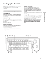
Setting up the Main Unit Hooking up the Main Unit Before hooking up the Main Unit, be sure the power cord is unplugged. Refer to the figures below for the connections. Source component hookups AUDIO IN jack (A) Hook up the audio output of each source component and the AUDIO IN jack of each SOURCE connection jack of the Main Unit. Use RCA audio cables. VIDEO IN jack (B) Hook up the video output of each source component and the VIDEO IN jack of each SOURCE connection jack of the Main Unit. Use an RCA video cable. RS232C connector (C) Hook up any RS232C equipped source component and the RS232C connector of the Main Unit. Use an RS232C cross cable. You can control the connected RS232C components (ex. DVP-CX777ES, STR-DA5000ES) from the Main Unit by sending commands. CONTROL A1II jack (D) Hook up each CONTROL A1II jack of the source equipment such as CDP-CX455 and the Main Unit. Use a CONTROL A1II cable. However, you cannot hook up another component to CDP-CX455 with a CONTROL A1II cable. You can control the connected source component from the Main Unit. IR OUT jack (E) Plug the IR emitter into the IR OUT jack of each SOURCE connection jack of the Main Unit. Be careful to match the source audio and video connection number on the Main Unit to the IR emitter connector number. The IR control signal will be routed to the correct source component. Find the IR sensor window on the source component and attach the emitter to the component sensor. AMBEGF HDL ANTENNA IR OUT IR OUT IR OUT IR OUT IR OUT IR OUT IR OUT IR OUT IR OUT COMMON 12V TRIGGER VIDEO IN VIDEO OUT VIDEO IN VIDEO OUT VIDEO IN VIDEO OUT VIDEO IN VIDEO OUT VIDEO IN VIDEO OUT VIDEO IN VIDEO OUT VIDEO IN VIDEO OUT VIDEO IN VIDEO OUT AUDIO IN AUDIO OUT AUDIO IN AUDIO OUT AUDIO IN AUDIO OUT AUDIO IN AUDIO OUT AUDIO IN AUDIO OUT AUDIO IN AUDIO OUT AUDIO IN AUDIO OUT AUDIO IN AUDIO OUT L L L L L L L L CONTROL A1 II R R R R R R R R SOURCE 1 SOURCE 2 SOURCE 3 SOURCE 4 SOURCE 5 SOURCE 6 SOURCE 7 SOURCE 8 123 456 STR KEYPAD R L KEYPAD R L KEYPAD R L KEYPAD R L KEYPAD R L KEYPAD R L FIXED PRE OUT R VIDEO OUT L FIXED PRE OUT R VIDEO OUT L FIXED PRE OUT R VIDEO OUT L FIXED PRE OUT R VIDEO OUT L VARIABLE PRE OUT R VIDEO OUT L VARIABLE PRE OUT R VIDEO OUT L SPEAKERS (CLASS 2 WIRING) ZONE 1 SPEAKERS (CLASS 2 WIRING) ZONE 2 SPEAKERS (CLASS 2 WIRING) ZONE 3 SPEAKERS (CLASS 2 WIRING) ZONE 4 SPEAKERS (CLASS 2 WIRING) ZONE 5 SPEAKERS (CLASS 2 WIRING) ZONE 6 DVP AUX RS232C SPEAKERS IMPEDANCE USE 4-16 K IJ C ~AC IN N 17US
-
 1
1 -
2
-
3
-
4
-
5
-
6
-
7
-
8
-
9
-
10
-
11
-
 12
12 -
 13
13 -
 14
14 -
 15
15 -
 16
16 -
 17
17 -
 18
18 -
 19
19 -
 20
20 -
 21
21 -
 22
22 -
23
-
24
-
25
-
26
-
27
-
28
-
29
-
30
-
31
-
32
-
33
-
34
-
35
-
36
-
37
-
38
-
39
-
40
-
41
-
42
-
43
-
44
 |
 |
