Sony CPD-G420 Operating Instructions (primary manual) - Page 5
Identifying parts and controls, Front - usb
 |
View all Sony CPD-G420 manuals
Add to My Manuals
Save this manual to your list of manuals |
Page 5 highlights
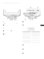
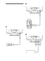
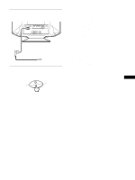
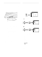
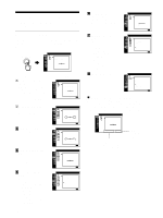
Identifying parts and controls See the pages in parentheses for further details. Front INPUT PICTURE EFFECT MENU 1 2 OK Rear forward side forward side rear side 2R G B HD VD 1 AC IN rear side 1 INPUT (input) switch (page 9) This switch selects the INPUT 1 (video input 1 connector: y1) or INPUT 2 (video input 2 connector: y2). 2 PICTURE EFFECT button (page 11) This button is used to change the preset picture effects' modes. 3 MENU button (page 10) This button is used to display or close the menu. 4 Control button (OK, M/m) (page 11) This button is used to make adjustments to the monitor and call up the CONTRAST menu directly. 5 ! (power) switch and indicator (pages 7, 18, 22) This button turns the monitor on and off. The power indicator lights up in green when the monitor is turned on, and lights up in orange when the monitor is in power saving mode. 6 Video input 2 connector (BNC) (page 6) This connector inputs RGB video signals (0.700 Vp-p, positive) and sync signals. 7 Video input 1 connector (HD15) (page 6) US This connector inputs RGB video signals (0.700 Vp-p, positive) and sync signals. 54321 10 9 8 7 6 15 14 13 12 11 Pin No. Signal 1 Red 2 Green (Sync on Green) 3 Blue 4 ID (Ground) 5 DDC Ground* 6 Red Ground 7 Green Ground 8 Blue Ground Pin No. Signal 9 DDC + 5V* 10 Ground 11 ID (Ground) 12 Bi-Directional Data (SDA)* 13 H. Sync 14 V. Sync 15 Data Clock (SCL)* * DDC (Display Data Channel) is a standard of VESA. 8 USB (universal serial bus) downstream connectors (page 8) Use these connectors to link USB peripheral devices to the monitor. 9 USB (universal serial bus) upstream connector (page 8) Use this connector to link the monitor to a USB compliant computer. q; AC IN connector (page 7) This connector provides AC power to the monitor. 5
-
 1
1 -
 2
2 -
 3
3 -
 4
4 -
 5
5 -
 6
6 -
 7
7 -
 8
8 -
 9
9 -
 10
10 -
 11
11 -
12
-
13
-
14
-
15
-
16
-
17
-
18
-
19
-
20
-
21
-
22
-
23
-
24
-
25
-
26
-
27
-
28
-
29
-
30
-
31
-
32
-
33
-
34
-
35
-
36
-
37
-
38
-
39
-
40
-
41
-
42
-
43
-
44
-
45
-
46
-
47
-
48
-
49
-
50
-
51
-
52
-
53
-
54
-
55
-
56
-
57
-
58
-
59
-
60
-
61
-
62
-
63
-
64
-
65
-
66
-
67
-
68
-
69
-
70
 |
 |
