Sony CPD-G420 Operating Instructions (primary manual) - Page 6
Setup, Step 1: Connect your monitor to your computer, Step 1:Connect your monitor to, your computer
 |
View all Sony CPD-G420 manuals
Add to My Manuals
Save this manual to your list of manuals |
Page 6 highlights
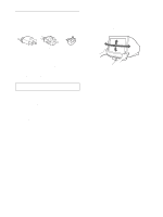
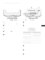
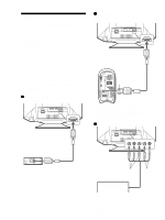
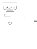
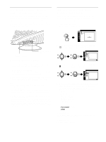
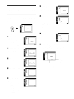
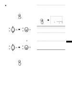
Setup Before using your monitor, check that the following accessories are included in your carton: • Power cord (1) • HD15 video signal cable (1) • USB cable (1) • Exclusive Power Mac G3/G4 adapter (1) • Warranty card (1) • Notes on cleaning the screen's surface (1) • This instruction manual (1) Step 1: Connect your monitor to your computer Turn off the monitor and computer before connecting. Notes • Do not touch the pins of the video signal cable connector as this might bend the pins. • When connecting the video signal cable, check the alignment of the HD15 connector. Do not force the connector in the wrong way or the pins might bend. x Connecting to an IBM PC/AT or compatible computer 2R G B HD VD 1 AC IN to HD15 x Connecting to a Macintosh or compatible computer Use the supplied exclusive Power Mac G3/G4 adapter. 2R G B HD VD 1 AC IN to HD15 Power Mac G3/G4 exclusive Power Mac G3/G4 adapter (supplied)* to video output video signal cable (supplied) * Connect the supplied adapter to the computer before connecting the cable. This adapter is compatible only with Power Mac G3/G4 computers that have 3 rows of pins. If you connect to the other version of Macintosh series computer that has 2 rows of pins, you will need a different adapter (not supplied). x Connecting to the 5 BNC connectors 2R G B HD VD 1 AC IN IBM PC/AT or compatible computer to video output video signal cable (supplied) 6 to R/G/B input to HD/VD input Refer to the preceding examples to connect to your computer. video signal cable (SMF-400, not supplied)* * Connect the cables from left to right in the following order: Red-GreenBlue-HD-VD. Note Plug & Play (DDC) does not apply to the 5 BNC connectors. If you want to use Plug & Play, connect your computer to the connector using the supplied video signal cable.
-
 1
1 -
 2
2 -
 3
3 -
 4
4 -
 5
5 -
 6
6 -
 7
7 -
 8
8 -
 9
9 -
 10
10 -
 11
11 -
 12
12 -
13
-
14
-
15
-
16
-
17
-
18
-
19
-
20
-
21
-
22
-
23
-
24
-
25
-
26
-
27
-
28
-
29
-
30
-
31
-
32
-
33
-
34
-
35
-
36
-
37
-
38
-
39
-
40
-
41
-
42
-
43
-
44
-
45
-
46
-
47
-
48
-
49
-
50
-
51
-
52
-
53
-
54
-
55
-
56
-
57
-
58
-
59
-
60
-
61
-
62
-
63
-
64
-
65
-
66
-
67
-
68
-
69
-
70
 |
 |
