Sony STR-D1015 Operating Instructions - Page 6
Hookups
 |
View all Sony STR-D1015 manuals
Add to My Manuals
Save this manual to your list of manuals |
Page 6 highlights
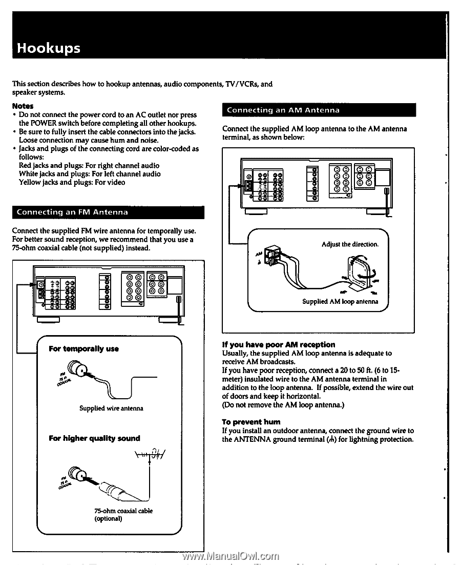
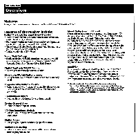
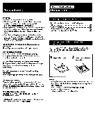
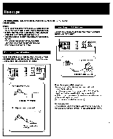
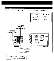
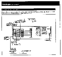
Hookups This section describes how to hookup antennas, audio components, TV/VCRs, and speaker systems. Notes • Do not connect the power cord to an AC outlet nor press the POWER switch before completing all other hookups. • Be sure to fully insert the cable connectors into the jacks. Loose connection may cause hum and noise. • Jacks and plugs of the connecting cord are color-coded as follows: Red jacks and plugs: For right channel audio White jacks and plugs: For left channel audio Yellow jacks and plugs: For video Connecting an AM Antenna Connect the supplied AM loop antenna to the AM antenna terminal, as shown below: 02 00 R1 N•Pf OO OO 88 4:1 Connecting an FM Antenna Connect the supplied FM wire antenna for temporally use. For better sound reception, we recommend that you use a 75-ohm coaxial cable (not supplied) instead. Adjust the direction. M.1 0 00 0 KA c0)c8) 43 Supplied AM loop antenna I For temporally use Supplied wire antenna For higher quality sound \ \,1 f you have poor AM reception Usually, the supplied AM loop antenna is adequate to receive AM broadcasts. If you have poor reception, connect a 20 to 50 ft. (6 to 15meter) insulated wire to the AM antenna terminal in addition to the loop antenna. If possible, extend the wire out of doors and keep it horizontal. (Do not remove the AM loop antenna.) To prevent hum If you install an outdoor antenna, connect the ground wire to the ANTENNA ground terminal (A) for lightning protection. 75-ohm coaxial cable (optional)
-
 1
1 -
 2
2 -
 3
3 -
 4
4 -
 5
5 -
 6
6 -
 7
7 -
 8
8 -
 9
9 -
 10
10 -
 11
11 -
 12
12 -
13
-
14
-
15
-
16
-
17
-
18
-
19
-
20
-
21
-
22
-
23
-
24
-
25
-
26
-
27
-
28
-
29
-
30
-
31
-
32
-
33
-
34
-
35
-
36
-
37
-
38
-
39
-
40
 |
 |