Sony STR-D1090 Operating Instructions - Page 6
Hooking, System
 |
View all Sony STR-D1090 manuals
Add to My Manuals
Save this manual to your list of manuals |
Page 6 highlights
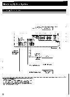
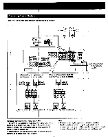
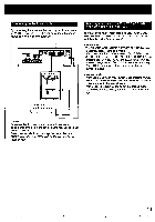
Hooking Up the System At first, this section describes about the antenna connection and then the connection with the other equipment. After that, it shows about the speaker connection and about the AC outlet. The STR-D2090 has the AMP MODE selector and the SURROUND OUT jacks on the rear panel. The illustrations described on the connections are the STR-D2090. • Do not connect the power cord to an AC outlet nor press the POWER switch before accomplishing all other connections. • The cable connectors should be fully inserted into the jacks. Loose connection may cause hum and noise. • Jacks and plugs of the connecting cord are color-coded as follows: Red jacks and plugs: For the right channel of audio signals White jacks and plugs: For the left channel of audio signals Yellow jacks and plugs: For video signals Connecting an AM Antenna The AM broadcast is enough received with the supplied AM loop antenna. However, the connection of insulated wire is also available for areas with difficult AM reception. 5- 03 a 02 Adjust the direction. Connecting an FM Antenna Though the wire antenna is supplied with this unit, the higher quality sound will be obtained with the 75-ohm coaxial cable. PJ_ 03 For normal use sgijcifrx Supplied AM loop antenna For areas with difficult AM reception In areas with troubled reception, connect a 6 to 15-meter (20 to 50-feet) insulated wire to the AM antenna terminal. Extend this out of doors if possible, keeping the greater portion horizontal. (There is no need to disconnect the supplied antenna.) To prevent hum Connect the ground wire to ANTENNA ground terminal (k). When an outdoor antenna is installed, be sure to connect the ground wire for lightning protection. Supplied wire antenna For higher quality sound Sgoct 75-ohm coaxial cable (optional) 6
-
 1
1 -
 2
2 -
 3
3 -
 4
4 -
 5
5 -
 6
6 -
 7
7 -
 8
8 -
 9
9 -
 10
10 -
 11
11 -
 12
12 -
13
-
14
-
15
-
16
-
17
-
18
-
19
-
20
-
21
-
22
-
23
-
24
-
25
-
26
-
27
-
28
-
29
-
30
-
31
-
32
-
33
-
34
-
35
-
36
-
37
-
38
-
39
-
40
-
41
-
42
-
43
-
44
-
45
-
46
-
47
-
48
-
49
-
50
-
51
 |
 |
