Stihl FS 560 C-EM Product Instruction Manual - Page 20
molding 6 line up with the slots
 |
View all Stihl FS 560 C-EM manuals
Add to My Manuals
Save this manual to your list of manuals |
Page 20 highlights
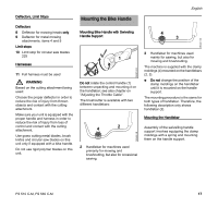
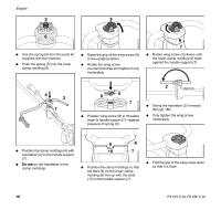
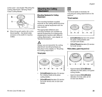
English 5 8 3BA010 KN N Use the spring (5) from the parts kit supplied with the machine. N Push the spring (5) into the lower clamp molding (6). 3BA005 KN N Raise the grip of the wing screw (8) to the upright position. N Rotate the wing screw counterclockwise and tighten it only moderately. 3BA007 KN 6 7 N Rotate wing screw clockwise until the lower clamp molding (6) butts against the handle support (7). 4 2 7 8 5 7 N Position wing screw (8) in threaded insert in handle support (7) - against pressure of spring (5). 3BA008 KN 2 N Swing the handebar (2) forwards through 180°. N Only tighten the wing screw moderately. 4900BA003 KN 4900BA002 KN 4900BA004 KN N Position the clamp moldings (4) with handlebar (2) on the handle support (7). N Do notturn the handlebar in the clamp moldings. 9 6 10 7 N Position the clamp moldings so that the tabs (9) on the lower clamp molding (6) line up with the slots (10) in the handle support (7). 3BA0009 KN N Fold the grip of the wing screw down so that it is flush. 18 FS 510 C-M, FS 560 C-M
-
 1
1 -
2
-
3
-
4
-
5
-
6
-
7
-
8
-
9
-
10
-
11
-
12
-
13
-
14
-
 15
15 -
 16
16 -
 17
17 -
 18
18 -
 19
19 -
 20
20 -
 21
21 -
 22
22 -
 23
23 -
 24
24 -
 25
25 -
26
-
27
-
28
-
29
-
30
-
31
-
32
-
33
-
34
-
35
-
36
-
37
-
38
-
39
-
40
-
41
-
42
-
43
-
44
-
45
-
46
-
47
-
48
-
49
-
50
-
51
-
52
-
53
-
54
-
55
-
56
-
57
-
58
-
59
-
60
-
61
-
62
-
63
-
64
-
65
-
66
-
67
-
68
-
69
-
70
-
71
-
72
-
73
-
74
-
75
-
76
-
77
-
78
-
79
-
80
-
81
-
82
-
83
-
84
-
85
-
86
-
87
-
88
-
89
-
90
-
91
-
92
-
93
-
94
-
95
-
96
-
97
-
98
-
99
-
100
-
101
-
102
-
103
-
104
-
105
-
106
-
107
-
108
-
109
-
110
-
111
-
112
-
113
-
114
-
115
-
116
-
117
-
118
-
119
-
120
 |
 |
