Thermador UCVP36XS Installation Instructions - Page 14
Prepare downdraft housing, Installation with gas cooktops
 |
View all Thermador UCVP36XS manuals
Add to My Manuals
Save this manual to your list of manuals |
Page 14 highlights
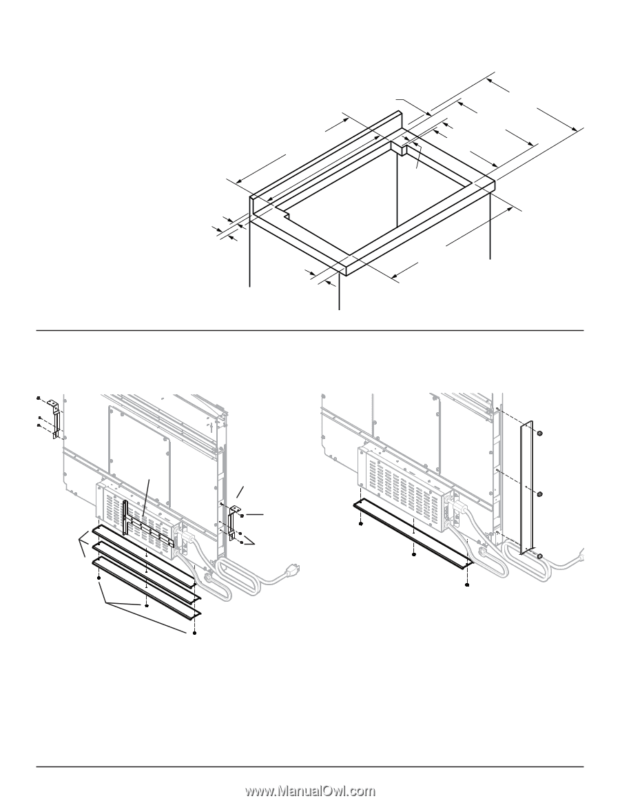
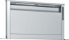
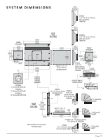
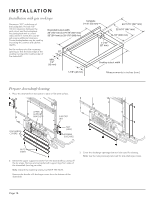
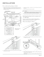
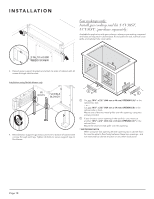
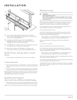
I N S TA L L AT I O N Installation with gas cooktops Dimension "BT" is thickness of the backsplash. Provide 1/2" (13 mm) clearance between the vent cutout and the backsplash. Any backsplash with a curved radius where it meets the counter will require additional clearance. Thicker backsplashes may be used by increasing the counter and cabinet depths. Downdraft cutout width: 30" (762 mm) is 27-1/16" (687 mm) 36" (914 mm) is 33-1/16" (840 mm) Template 2-1/8" (54 mm) 1-1/16" (27 mm) 24-11/16" (627 mm) 22-5/16" (567 mm) 19-1/8" (486 mm) Set the cooktop into the coutertop opening so that the back edge of the cooktop overlaps the leading edge of the downdraft. BT MIN. 1/2" (13 mm) Cooktop cutout width 1-7/8" (48 mm) Measurements in inches (mm). Prepare downdraft housing 1. Place the downdraft on its back on a table or lat work surface. UPPER SUPPORT BRACKETS DISCHARGE COVERS SUPPORT LEG NUT (KEEP) SCREWS (DISCARD) NUTS (KEEP) 2. Detach the upper support brackets from the downdraft by cutting off the tie wraps. Remove and set aside both support legs from sides of the downdraft (one leg per side). Note: Discard the retaining screws, but KEEP THE NUTS. Remove the bundle of 3 dischage covers from the bottom of the downdraft. 3. Cover the discharge openings that won't be used for ducting. Note: Use the nuts previously removed for side discharge covers. Page 14
-
 1
1 -
2
-
3
-
4
-
5
-
6
-
7
-
8
-
 9
9 -
 10
10 -
 11
11 -
 12
12 -
 13
13 -
 14
14 -
 15
15 -
 16
16 -
 17
17 -
 18
18 -
 19
19 -
20
-
21
-
22
-
23
-
24
-
25
-
26
-
27
-
28
-
29
-
30
-
31
-
32
-
33
-
34
-
35
-
36
-
37
-
38
-
39
-
40
-
41
-
42
-
43
-
44
-
45
-
46
-
47
-
48
-
49
-
50
-
51
-
52
-
53
-
54
-
55
-
56
-
57
-
58
-
59
-
60
-
61
-
62
-
63
-
64
 |
 |