Thermador UCVP36XS Installation Instructions - Page 9
Plan The Installation
 |
View all Thermador UCVP36XS manuals
Add to My Manuals
Save this manual to your list of manuals |
Page 9 highlights
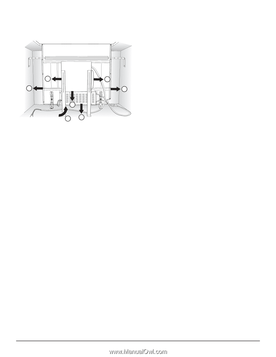
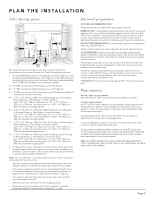
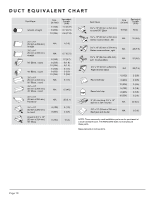
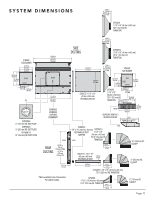
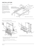
PLAN THE INSTALLATION Select ducting option A D B E C F G HD1101 The 6 basic discharge connections, left, right, rear, front, below and recirculation can be achieved through A to G with the optional parts listed. 1. The downdraft blower system is designed for use with 8" (203 mm) round ductwork using a lexible blower or 6" (152 mm) or 10" (254 mm) round ductwork using an inline or remote blower. (Purchase blowers separately.) Seven (7) different discharge connections are available: A = 8" (203 mm) Round, Left Discharge out of Flex Blower B = 8" (203 mm) Round, Right Discharge out of Flex Blower C = 8" (203 mm) Round, Down Discharge out of Flex Blower (Electrical Panel to be mounted remotely) D = 1-7/8" x 19" (48 mm x 483 mm), Left Discharge out of Housing to Remote Blower or Flex Blower in remote location. Use 1-7/8" x 19" (48mm x 483mm) to 6", 8", or 10" (152 mm, 203 mm, or 254 mm) round transition or 1-7/8" x 19" (48 mm x 483 mm) ductwork as appropriate. E = 1-7/8" x 19" (48 mm x 483 mm), Right Discharge out of Housing to Remote Blower or Flex Blower in remote location. Use 1-7/8" x 19" (48 mm x 483 mm) to 6", 8", or 10" (152 mm, 203 mm, or 254 mm) round transition or 1-7/8" x 19" (48 mm x 483 mm) ductwork as appropriate. F = 1-7/8" x 19" (48 mm x 483 mm), Rear Discharge out of Housing to Remote Blower or Flex Blower in remote location. Use 1-7/8" x 19" (48 mm x 483 mm) to 6", 8", or 10" (152 mm, 203 mm, or 254 mm) round transition or 1-7/8" x 19" (48 mm x 483 mm) ductwork as appropriate. G = 1-7/8" x 19" (48 mm x 483 mm), Down Discharge out of Housing to Remote Blower or Flex Blower in remote location. Use 1-7/8" x 19" (48 mm x 483 mm) to 6", 8", or 10" (152 mm, 203 mm, or 254 mm) round transition or 1-7/8" x 19" (48 mm x 483 mm) ductwork as appropriate. 2. For best performance: Choose the ducting option which allows the shortest length of ductwork and a minimum number of elbows and transitions. Check location of loor joists, wall studs, electrical wiring or plumbing for possible interference. Note: The manufacturer is not responsible for performance complaints attributable to the duct section. • The device achieves its optimum performance by means of a short, straight exhaust air duct and as large a pipe diameter as possible. • The optimum extraction performance is not achieved and fan noise is increased if exhaust air ducts are long and rough and if there is a large number of duct bends or diameters less than 6" (152 mm). • The pipes or hoses for laying the exhaust air line must consist of non-combustible material. • Seal the connection points of the ducts appropriately. • Ductwork must vent outside, not into attic spaces for example, unless the available 'Non-duct Recirculation Kit' is used. Ductwork preparation DUCTING RECOMMENDATIONS Proper performance is dependent upon proper ducting. MAKE-UP AIR: Local building codes may require the use of make-up air systems when using ducted ventilation systems greater than speciied CFM of air movement. The speciied CFM varies from locale to locale. It is the responsibility of the owner and the installer to determine if additional requirements and/or standards apply to speciic installations. DO NOT USE FLEXIBLE DUCT; it creates back pressure/ air turbulence and reduces performance. Always install a metal vent cover where the ductwork exits the house. COLD WEATHER installations should have an additional backdraft damper installed to minimize backward cold air low and a nonmetallic thermal break to minimize conduction of outside temperatures as part of the ductwork. The damper should be on the cold air side of the thermal break. The break should be as close as possible to where the ducting enters the heated portion of the house. For safety reasons, ducting should vent directly outdoors (not into an attic, underneath the house, into the garage or into any enclosed space). In gas cooking applications, the unit cannot be used in conjunction with a recirculation unit. THERMADOR® recommends not exceeding 50 ft. (15 m) of equivalent duct. Plan cabinetry For left, right, or rear exhaust: Allow at least 18" (457 mm) for transition and elbow or blower. For left / right exhaust: A 30" (762 mm) deep cabinet is recommended to align properly with lex blower. Flex blower can be mounted to rear cabinet wall or to a platform / frame (not provided) on the base of the cabinet loor. (See lex blower instructions.) Cabinet depths of 24" (610 mm) to 30" (762 mm) are required depending on the type of cooking appliance. For some applications, gas or electrical connections will need to be moved or routed around downdraft unit. For gas cooktop installations make sure that a minimum 27 square inch (174 cm²) opening is provided in the toe-kick and cabinet base. Inadequate ventilation of the cabinet below the cooktop may result in lame outage when operating the fan on higher speeds. Note: A cooktop sealing kit must be purchased for gas applications. The kit includes hole covers for the toe-kick and cabinet base, as well as a trim seal for the cooktop. Page 9
-
 1
1 -
2
-
3
-
 4
4 -
 5
5 -
 6
6 -
 7
7 -
 8
8 -
 9
9 -
 10
10 -
 11
11 -
 12
12 -
 13
13 -
 14
14 -
15
-
16
-
17
-
18
-
19
-
20
-
21
-
22
-
23
-
24
-
25
-
26
-
27
-
28
-
29
-
30
-
31
-
32
-
33
-
34
-
35
-
36
-
37
-
38
-
39
-
40
-
41
-
42
-
43
-
44
-
45
-
46
-
47
-
48
-
49
-
50
-
51
-
52
-
53
-
54
-
55
-
56
-
57
-
58
-
59
-
60
-
61
-
62
-
63
-
64
 |
 |