Thermador UCVP36XS Installation Instructions - Page 8
Before You Begin
 |
View all Thermador UCVP36XS manuals
Add to My Manuals
Save this manual to your list of manuals |
Page 8 highlights
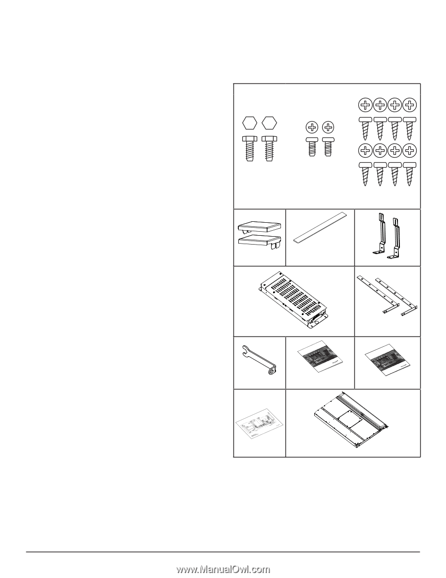
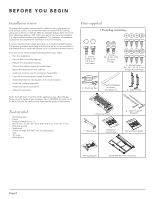
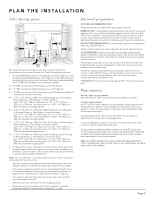
BEFORE YOU BEGIN Installation review This downdraft system can be used to exhaust cooking by-products such as heat, steam, and smoke that may be created while cooking using gas or electric cooktops. With its versatile design, there are six (6) basic discharge options - left, right, rear, below, front and recirculation. It is important to irst plan your installation. The purchase of additional accessories to complete the installation may be necessary. It can be mounted in an island, peninsula, or conventional wall location. The blower (purchase separately) and electrical panel can be mounted to the downdraft unit, inside the cabinet, or in a convenient remote location. This unit can be easily installed following these basic steps: • Plan the installation. • Cut out the countertop opening. • Prepare the downdraft housing. • Cut out the cabinet opening for discharge. • Mount the downdraft in the cabinet. • Install gas cooktop seal kit accessory, if applicable. • Connect the ductwork and install the blower. • Install downdraft electrical panel, if in remote location. • Install the cooking appliance. • Install end caps to downdraft. • Check the operation. Note: the high level of air low of this appliance may effect the gas lame on some types of gas cooktops. This is NORMAL and will cause no harm, but can be corrected by lowering the speed of the blower. Parts supplied 1 Parts Bag containing: 2 - Screws, 1/4-20 x .50 (12.7 mm) Hex Head 2 - Screws, No. 8-18 x .375 (9.5 mm) Phillips 8 - Wood Screws, No. 10 x .50 (12.7 mm) Phillips Round Head 2 - End Cap Trim 1 - Plastic installation template (see page 13) 2 - Support legs Tools needed • Measuring tape • Pencil • Phillips screwdriver no. 2 • Nut drivers - 11/32" (8.7 mm), 3/8" (9.5 mm), 7/16" (11.1 mm) • Box-end wrench • Spirit-level • Aluminum tape (DO NOT use insulating tape) • Saw • Tin snips • Work gloves 1 - Electrical Panel 1 - Special key INMSMATAANLNULUEALATLDIO'DINNESMITNAASNLTULAAALTLAIOCINÓN MVAESVNTEETNRITLPIALITAEEDCUOER®RSSDEEERNITCEIASRSODTODRWEÉSSNCDSERÉNRADFIEETNMVTAEESNTSTEEILRRAPITEIOEMRCAESMDTERPIECE® Installation instructions 2 - Upper Support Brackets UGSEUEGTIAUDDÍNEA'EDDDN'CUETATRUIRLESEITOSIGAEYUTNCIIDOUEINDADO MAVSEVTNEETNRITLPIALITEAECDUEOR®RSSDEEERNICTEIASRSODTORDWÉESSNCDSERÉNRADFIEETNMVTAEESNTSTEIELRRAPITEIOEMRCAEMSDTERPIECE® Use and Care guide Wiring diagram Downdraft Ventilator Housing Page 8
-
 1
1 -
2
-
 3
3 -
 4
4 -
 5
5 -
 6
6 -
 7
7 -
 8
8 -
 9
9 -
 10
10 -
 11
11 -
 12
12 -
 13
13 -
14
-
15
-
16
-
17
-
18
-
19
-
20
-
21
-
22
-
23
-
24
-
25
-
26
-
27
-
28
-
29
-
30
-
31
-
32
-
33
-
34
-
35
-
36
-
37
-
38
-
39
-
40
-
41
-
42
-
43
-
44
-
45
-
46
-
47
-
48
-
49
-
50
-
51
-
52
-
53
-
54
-
55
-
56
-
57
-
58
-
59
-
60
-
61
-
62
-
63
-
64
 |
 |