Thermador UCVP36XS Installation Instructions - Page 16
Insert upper support brackets and attach
 |
View all Thermador UCVP36XS manuals
Add to My Manuals
Save this manual to your list of manuals |
Page 16 highlights
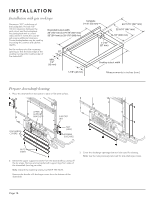
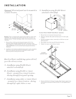
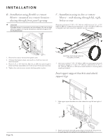
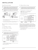
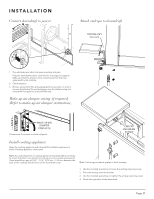
I N S TA L L AT I O N B - Installation using flexible or remote blower - mounted in a remote location ducting through front panel opening CAUTION If lexible blower is mounted as an inline blower: Do not use legs alone for support. It may be necessary to add extra support for the lexible blower. C - Installation using in-line or remote blower - with ducting through left, right, below or rear (Requires purchase of 1-7/8" x 19" (48 mm x 483 mm) to 6", 8", or 10" (152 mm, 203 mm, or 254 mm) round transition. 1-7/8" x 19" (48 mm x 483 mm) rectangular duct and connection adapters are also available.) 1. Remove hex nuts to remove front panel cover. 2. If blower discharge is down, remove (4) no. 8-32 hex nuts and electrical panel. 3. Place 6", 8", or 10" (152 mm, 203 mm, or 254 mm) round rough-in plate (purchase separately) over studs around front panel opening. 4. Tighten hex nuts to secure remote discharge plate in place. DUCTING OUT RIGHT SIDE OF HOUSING SHOWN. 1. Use nuts to connect 1-7/8" x 19" (48 mm x 483 mm) rectangular ductwork connection adapter or 1-7/8" x 19" (48 mm x 483 mm) to 6", 8", or 10" (152 mm, 203 mm, or 254 mm) round transition to housing when installing ductwork. Insert upper support brackets and attach support legs 1. Slide upper suport brackets into slide channel at top left and right of unit. Page 16 2. Attach previously removed support legs to downdraft using one nut for each leg. Do not tighten nut completely at this time.
-
 1
1 -
2
-
3
-
4
-
5
-
6
-
7
-
8
-
9
-
10
-
 11
11 -
 12
12 -
 13
13 -
 14
14 -
 15
15 -
 16
16 -
 17
17 -
 18
18 -
 19
19 -
 20
20 -
 21
21 -
22
-
23
-
24
-
25
-
26
-
27
-
28
-
29
-
30
-
31
-
32
-
33
-
34
-
35
-
36
-
37
-
38
-
39
-
40
-
41
-
42
-
43
-
44
-
45
-
46
-
47
-
48
-
49
-
50
-
51
-
52
-
53
-
54
-
55
-
56
-
57
-
58
-
59
-
60
-
61
-
62
-
63
-
64
 |
 |
