Thermador UCVP36XS Installation Instructions - Page 20
Install electrical wiring, Based on blower selected, go to the relevent, A - Flex blower
 |
View all Thermador UCVP36XS manuals
Add to My Manuals
Save this manual to your list of manuals |
Page 20 highlights
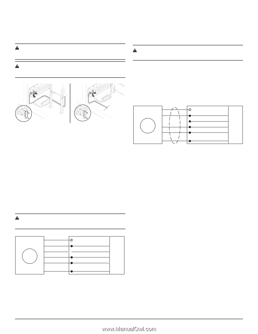
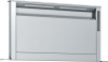
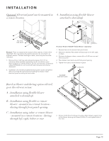
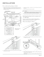
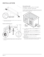
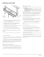
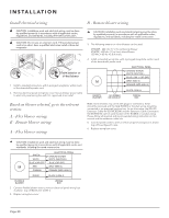
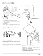
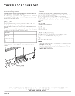
I N S TA L L AT I O N Install electrical wiring B - Remote blower wiring CAUTION: Installation work and electrical wiring must be done by qualiied person(s) in accordance with all applicable codes, regulations, and standards, including ire-rated construction. CAUTION: Do not use an extension cord. If the product power cord is too short, have a qualiied electrician install a three slot receptacle. From exterior or in-line blower 1. Install a standard wiring box, with 3-pronged receptacle, within reach of the downdraft's power cord. 2. Remove electrical panel wiring box cover. Secure blower power cable to electrical panel wiring box with U.L. approved strain relief. Based on blower selected, go to the relevent section: A - Flex blower wiring B - Remote blower wiring A - Flex blower wiring CAUTION: Installation work and electrical wiring must be done by qualiied person(s) in accordance with all applicable codes, regulations, and standards, including ire-rated construction. 3. The following exterior or inline blowers can be used: VTR630P - 600 cfm (17 m3/min) Remote Blower VTI610P - 600 cfm (17 m3/min) Inline Blower 120 VAC • 60 Hz • 5.0 A (max.) 4. Install a standard wiring box, with 3-pronged receptacle, within reach of the downdraft's power cord. ELECTRICAL PANEL GROUND SCREW WHITE (NEUTRAL) BLUE (LOW 1, CAP OFF) M GRAY (MED 2) ORANGE (MED-HIGH 3) BLACK (HIGH 4) REMOTE BLOWER 14/4 ROMEX OR CONDUIT WIRING BOX Note: Some blowers may come with plugs or connectors, these should be removed and the 14/4 ROMEX or Conduit wiring should be connected in an approved junction box. As an alternative, the BSH 25' Extension Cable Kit (EXTNCB25W) and the Extension Cable Connection Kit (EXTNSET4) can be used in place of the ROMEX or conduit wiring. Please follow all required and recommended wiring instructions in this manual and the extension cable kits. 5. Connect power wires to wires in electrical panel wiring box as shown. Cap off Low (Speed 1) wire. 6. Replace wiring box cover. CAUTION: Installation work and electrical wiring must be done by qualiied person(s) in accordance with all applicable codes and standards, including ire-rated construction. GREEN WHITE ELECTRICAL PANEL GROUND SCREW WHITE (NEUTRAL) BLUE (CAP OFF) BLUE (CAP OFF) M RED GRAY (MED 2) ORANGE ORANGE (MED-HIGH 3) BLACK BLACK (HIGH 4) FLEXIBLE BLOWER WIRING BOX 3. Connect lexible blower wires to wires in electrical panel wiring box as shown. Cap off BLUE wire (LOW 1). 4. Replace wiring box cover. Page 20
-
 1
1 -
2
-
3
-
4
-
5
-
6
-
7
-
8
-
9
-
10
-
11
-
12
-
13
-
14
-
 15
15 -
 16
16 -
 17
17 -
 18
18 -
 19
19 -
 20
20 -
 21
21 -
 22
22 -
 23
23 -
 24
24 -
 25
25 -
26
-
27
-
28
-
29
-
30
-
31
-
32
-
33
-
34
-
35
-
36
-
37
-
38
-
39
-
40
-
41
-
42
-
43
-
44
-
45
-
46
-
47
-
48
-
49
-
50
-
51
-
52
-
53
-
54
-
55
-
56
-
57
-
58
-
59
-
60
-
61
-
62
-
63
-
64
 |
 |