Tripp Lite S3M60K60K6T Owners Manual S3M 3-Phase UPS Systems for Models S3M25- - Page 24
Single UPS Installation
 |
View all Tripp Lite S3M60K60K6T manuals
Add to My Manuals
Save this manual to your list of manuals |
Page 24 highlights
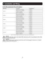
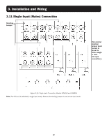
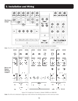
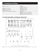
3. Installation and Wiring 3.10 Single UPS Installation Installation and wiring must be performed in accordance with local electrical codes/regulations and should only be performed by qualified personnel. 1. Ensure the mains wire and breakers in the building can sustain the rated capacity of the UPS to avoid electric shock or fire hazard. Note: Using a wall receptacle as the input power source for the UPS may result in the receptacle burning or being destroyed. 2. Switch off the mains switch in the building prior to installation. 3. Turn off all the connected devices before connecting to the UPS. 4. Prepare the power cables according to the tables below. Use the recommended installed screw torque, UPS input breaker sizes and battery cabinet batteries and breaker sizes as shown. 3.10.1 Power Cables The cable design must comply with the voltages and currents provided in this section. Installation and wiring must be performed in accordance with local electrical codes/regulations and should only be performed by qualified personnel. WARNING! Before starting, ensure you are aware of the location and operation of the external isolators which are connected to the UPS input/bypass supply of the mains distribution panel. Check to see if these supplies are electrically isolated. Post any necessary warning signs to prevent any inadvertent operation. UPS Models S3M25K S3M30K S3M50K S3M60K S3M80K S3M100K AC Input (mm2) L N 25 Max. 35 50 Max. 50 35 Max. 35 50 Max. 50 70 Max. 70 120 Max. 120 95 Max. 95 70*2 Max. 150 120 Max. 120 95*2 Max. 95*2 150 Max. 150 120*2 Max. 120*2 Cable Dimensions (mm²) AC Output (mm2) DC Input (mm2) L N +/- N 25 Max. 35 50 Max. 50 50 Max. 70 50 Max. 70 35 Max. 35 50 Max. 50 50 Max. 70 50 Max. 70 50 Max. 70 95 Max. 95 120 Max. 120 95 Max. 95 70 Max. 70 120 Max. 120 150 Max. 150 120 Max. 120 95 Max. 95 70*2 Max. 70*2 185 Max. 185 70*2 Max. 70*2 120 Max. 120 95*2 Max. 95*2 120*2 Max. 120*2 95*2 Max. 95*2 Grounding (mm2) 16 Max. 25 25 Max. 25 35 Max. 35 50 Max. 50 70 Max. 70 95 Max. 95 UPS Models S3M25K S3M30K S3M50K S3M60K S3M80K S3M100K Cable Dimensions (AWG) AC Input AC Output DC Input L N L N +/- N 4 AWG 1/0 AWG 4 AWG 1/0 AWG 1/0 AWG 1/0 AWG Max. 4 AWG Max. 1/0 AWG Max. 4 AWG Max. 1/0 AWG Max. 2/0 AWG Max. 2/0 AWG 2AWG 1/0 2 AWG 1/0 AWG 1/0 AWG 1/0 AWG Max. 2 AWG Max. 1/0 AWG Max. 2 AWG Max. 1/0 AWG Max. 2/0 AWG Max. 2/0 AWG 2/0 AWG 4/0 AWG 1/0 AWG 3/0 AWG 4/0 AWG 3/0 AWG Max. 2/0 AWG Max. 4/0 AWG Max. 2/0 AWG Max. 3/0 AWG Max. 4/0 AWG Max. 3/0 AWG 3/0 AWG 2/0 AWG*2 2/0 AWG 4/0 AWG 2/0 AWG*2 4/0 AWG Max. 3/0 AWG Max. 2/0 AWG Max. 2/0 AWG Max. 4/0 AWG Max. 2/0 AWG*2 Max. 4/0 AWG 4/0 AWG 3/0 AWG*2 3/0 AWG 2/0 AWG*2 3/0 AWG*2 2/0 AWG*2 Max. 4/0 AWG Max. 3/0 AWG*2 Max. 3/0 AWG Max. 2/0 AWG*2 Max. 3/0 AWG*2 Max. 2/0 AWG*2 2/0 AWG*2 4/0 AWG*2 4/0 AWG 3/0 AWG*2 4/0 AWG*2 3/0 AWG*2 Max. 150 Max. 4/0 AWG*2 Max. 4/0 AWG Max. 3/0 AWG*2 Max. 120*2 Max. 3/0 AWG*2 Table 3.1: Recommended Cross-Sectional Areas for Power Cables Grounding 5 AWG Max. 4 AWG 4 AWG Max. 4 AWG 2AWG Max. 2AWG 1/0 AWG Max. 1/0 AWG 2/0 AWG Max. 2/0 AWG 3/0 AWG Max. 3/0 AWG 24
-
 1
1 -
2
-
3
-
4
-
5
-
6
-
7
-
8
-
9
-
10
-
11
-
12
-
13
-
14
-
15
-
16
-
17
-
18
-
 19
19 -
 20
20 -
 21
21 -
 22
22 -
 23
23 -
 24
24 -
 25
25 -
 26
26 -
 27
27 -
 28
28 -
 29
29 -
30
-
31
-
32
-
33
-
34
-
35
-
36
-
37
-
38
-
39
-
40
-
41
-
42
-
43
-
44
-
45
-
46
-
47
-
48
-
49
-
50
-
51
-
52
-
53
-
54
-
55
-
56
-
57
-
58
-
59
-
60
-
61
-
62
-
63
-
64
-
65
-
66
-
67
-
68
-
69
-
70
-
71
-
72
-
73
-
74
-
75
-
76
-
77
-
78
-
79
-
80
-
81
-
82
-
83
-
84
-
85
-
86
-
87
-
88
-
89
-
90
-
91
-
92
-
93
-
94
-
95
-
96
-
97
-
98
-
99
-
100
-
101
-
102
-
103
-
104
-
105
-
106
-
107
-
108
-
109
-
110
-
111
-
112
-
113
-
114
-
115
-
116
-
117
-
118
-
119
-
120
-
121
-
122
-
123
-
124
-
125
-
126
-
127
-
128
-
129
-
130
-
131
-
132
-
133
-
134
-
135
-
136
-
137
-
138
-
139
-
140
-
141
-
142
-
143
-
144
-
145
-
146
-
147
-
148
-
149
-
150
-
151
-
152
-
153
-
154
-
155
-
156
-
157
-
158
-
159
-
160
-
161
-
162
-
163
-
164
-
165
-
166
-
167
-
168
-
169
-
170
-
171
-
172
-
173
-
174
-
175
-
176
-
177
-
178
-
179
-
180
-
181
-
182
-
183
-
184
-
185
-
186
-
187
-
188
-
189
-
190
-
191
-
192
-
193
-
194
-
195
-
196
-
197
-
198
-
199
-
200
-
201
-
202
-
203
-
204
-
205
-
206
-
207
-
208
-
209
-
210
-
211
-
212
-
213
-
214
-
215
-
216
-
217
-
218
-
219
-
220
-
221
-
222
-
223
-
224
-
225
-
226
-
227
-
228
-
229
-
230
-
231
-
232
-
233
-
234
-
235
-
236
-
237
-
238
-
239
-
240
-
241
-
242
-
243
-
244
-
245
-
246
-
247
-
248
 |
 |
