Tripp Lite S3M60K60K6T Owners Manual S3M 3-Phase UPS Systems for Models S3M25- - Page 73
Communications
 |
View all Tripp Lite S3M60K60K6T manuals
Add to My Manuals
Save this manual to your list of manuals |
Page 73 highlights
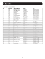
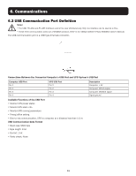
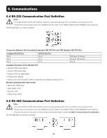
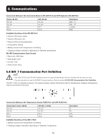
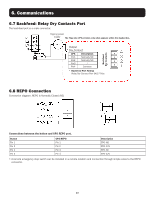
6. Communications 6.1 Web Management Card Tripp Lite's WEBCARDLX is an optional accessory available for all models. The WEBCARDLX card enables remote monitoring and control through several interfaces: HTML5 web via HTTP(S), menu/CLI via SSH/Telnet, and SNMP for integration with software management platforms, such as DCIM. Using WEBCARDLX in your UPS combined with Tripp Lite's network-enabled switched PDUs, you can manage power throughout your facility and receive automated alerts to identify problems before they cause downtime. WEBCARDLX also supports a family of sensors for remotely monitoring environmental conditions. You can link up to three sensors together, connecting them to a single port on the WEBCARDLX. Tripp Lite offers free PowerAlert® Network Management System software. Learn more and download at tripplite.com/products/power-alert. 6.1.1 WEBCARDLX Features The following is an introduction to the features of Tripp Lite's WEBCARDLX. To view the full description of the card's functionality, download its Owner's Manual at tripplite.com/support. A Ethernet Port: RJ45 jack connects the WEBCARDLX to the network using a standard Ethernet patch cable. The Link LED A1 and Status LED A2 indicate the operating conditions. B Micro-USB Port: Use this port to directly connect with a computer running a terminal emulation program. C Type-A USB Port: Use this port to connect a Tripp Lite ENVIROSENSE 2 module (E2MT, E2MTDO, E2MTDI, E2MTHDI) for a variety of environmental monitoring and control options. See tripplite.com for more information about these modules. Note: Do not connect a keyboard or mouse to this port. D Reset Button: The reset button is recessed, accessible through a small hole under the RJ45 network port. E Status LED: Shows WEBCARDLX status. 6.2 Relay Card A 10-pin terminal supports a relay card to provide bypass, utility failure, inverter on, battery low, UPS fault, UPS alarm and UPS shutdown functions. The relay communication card contains six dry contact outputs and one dry input. The inputs and outputs are factory programmed according to functions listed in the following table. Relay Contacts (Communication Card) Pin Function Description 1 Utility Failure 2 Battery Low 3 4 Bypass On 5 UPS Fault 6 Inverter On 7 Summary Alarm 8 Common 9 Remote Shutdown + Input or Output Output Input (5V to12V) 73
-
 1
1 -
2
-
3
-
4
-
5
-
6
-
7
-
8
-
9
-
10
-
11
-
12
-
13
-
14
-
15
-
16
-
17
-
18
-
19
-
20
-
21
-
22
-
23
-
24
-
25
-
26
-
27
-
28
-
29
-
30
-
31
-
32
-
33
-
34
-
35
-
36
-
37
-
38
-
39
-
40
-
41
-
42
-
43
-
44
-
45
-
46
-
47
-
48
-
49
-
50
-
51
-
52
-
53
-
54
-
55
-
56
-
57
-
58
-
59
-
60
-
61
-
62
-
63
-
64
-
65
-
66
-
67
-
 68
68 -
 69
69 -
 70
70 -
 71
71 -
 72
72 -
 73
73 -
 74
74 -
 75
75 -
 76
76 -
 77
77 -
 78
78 -
79
-
80
-
81
-
82
-
83
-
84
-
85
-
86
-
87
-
88
-
89
-
90
-
91
-
92
-
93
-
94
-
95
-
96
-
97
-
98
-
99
-
100
-
101
-
102
-
103
-
104
-
105
-
106
-
107
-
108
-
109
-
110
-
111
-
112
-
113
-
114
-
115
-
116
-
117
-
118
-
119
-
120
-
121
-
122
-
123
-
124
-
125
-
126
-
127
-
128
-
129
-
130
-
131
-
132
-
133
-
134
-
135
-
136
-
137
-
138
-
139
-
140
-
141
-
142
-
143
-
144
-
145
-
146
-
147
-
148
-
149
-
150
-
151
-
152
-
153
-
154
-
155
-
156
-
157
-
158
-
159
-
160
-
161
-
162
-
163
-
164
-
165
-
166
-
167
-
168
-
169
-
170
-
171
-
172
-
173
-
174
-
175
-
176
-
177
-
178
-
179
-
180
-
181
-
182
-
183
-
184
-
185
-
186
-
187
-
188
-
189
-
190
-
191
-
192
-
193
-
194
-
195
-
196
-
197
-
198
-
199
-
200
-
201
-
202
-
203
-
204
-
205
-
206
-
207
-
208
-
209
-
210
-
211
-
212
-
213
-
214
-
215
-
216
-
217
-
218
-
219
-
220
-
221
-
222
-
223
-
224
-
225
-
226
-
227
-
228
-
229
-
230
-
231
-
232
-
233
-
234
-
235
-
236
-
237
-
238
-
239
-
240
-
241
-
242
-
243
-
244
-
245
-
246
-
247
-
248
 |
 |
