Tripp Lite S3M60K60K6T Owners Manual S3M 3-Phase UPS Systems for Models S3M25- - Page 57
Parallel Settings
 |
View all Tripp Lite S3M60K60K6T manuals
Add to My Manuals
Save this manual to your list of manuals |
Page 57 highlights
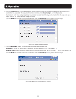
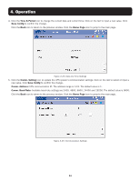
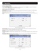
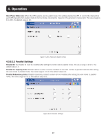
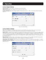
4. Operation Inter Power Walk in(s): When the UPS systems are in parallel mode, this setting enables the UPS to control the interval that each UPS transfers from battery mode to normal mode, reducing the impact on the generator or power grid. The value range is 1 to 200. The default value is 10. Figure 4-28C: Advanced System Setup 4.3.6.2.2 Parallel Settings Parallel ID: The Parallel ID must be modified after setting the work mode to parallel mode. The value range is 1 to 6. The default value is 1. Parallel for Capacity Units: Parallel cabinet number must be modified for the total number of parallel cabinets after setting the work mode to parallel mode. The value range is 2 to 6. The default value is 2. Parallel Redundancy Units: Parallel redundancy cabinet number can be modified after setting the work mode to parallel mode. The value range is 0 to 5. The default value is 0. Figure 4-29: Parallel Settings 57
-
 1
1 -
2
-
3
-
4
-
5
-
6
-
7
-
8
-
9
-
10
-
11
-
12
-
13
-
14
-
15
-
16
-
17
-
18
-
19
-
20
-
21
-
22
-
23
-
24
-
25
-
26
-
27
-
28
-
29
-
30
-
31
-
32
-
33
-
34
-
35
-
36
-
37
-
38
-
39
-
40
-
41
-
42
-
43
-
44
-
45
-
46
-
47
-
48
-
49
-
50
-
51
-
 52
52 -
 53
53 -
 54
54 -
 55
55 -
 56
56 -
 57
57 -
 58
58 -
 59
59 -
 60
60 -
 61
61 -
 62
62 -
63
-
64
-
65
-
66
-
67
-
68
-
69
-
70
-
71
-
72
-
73
-
74
-
75
-
76
-
77
-
78
-
79
-
80
-
81
-
82
-
83
-
84
-
85
-
86
-
87
-
88
-
89
-
90
-
91
-
92
-
93
-
94
-
95
-
96
-
97
-
98
-
99
-
100
-
101
-
102
-
103
-
104
-
105
-
106
-
107
-
108
-
109
-
110
-
111
-
112
-
113
-
114
-
115
-
116
-
117
-
118
-
119
-
120
-
121
-
122
-
123
-
124
-
125
-
126
-
127
-
128
-
129
-
130
-
131
-
132
-
133
-
134
-
135
-
136
-
137
-
138
-
139
-
140
-
141
-
142
-
143
-
144
-
145
-
146
-
147
-
148
-
149
-
150
-
151
-
152
-
153
-
154
-
155
-
156
-
157
-
158
-
159
-
160
-
161
-
162
-
163
-
164
-
165
-
166
-
167
-
168
-
169
-
170
-
171
-
172
-
173
-
174
-
175
-
176
-
177
-
178
-
179
-
180
-
181
-
182
-
183
-
184
-
185
-
186
-
187
-
188
-
189
-
190
-
191
-
192
-
193
-
194
-
195
-
196
-
197
-
198
-
199
-
200
-
201
-
202
-
203
-
204
-
205
-
206
-
207
-
208
-
209
-
210
-
211
-
212
-
213
-
214
-
215
-
216
-
217
-
218
-
219
-
220
-
221
-
222
-
223
-
224
-
225
-
226
-
227
-
228
-
229
-
230
-
231
-
232
-
233
-
234
-
235
-
236
-
237
-
238
-
239
-
240
-
241
-
242
-
243
-
244
-
245
-
246
-
247
-
248
 |
 |
