Tripp Lite S3M60K60K6T Owners Manual S3M 3-Phase UPS Systems for Models S3M25- - Page 34
Parallel Cable Installation
 |
View all Tripp Lite S3M60K60K6T manuals
Add to My Manuals
Save this manual to your list of manuals |
Page 34 highlights
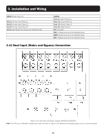
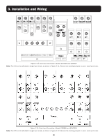
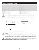
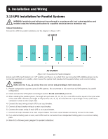
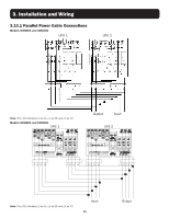
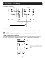
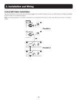
3. Installation and Wiring Models S3M80K and S3M100K UPS 1 UPS 2 Note: The LCD indicates L1 as (A), L2 as (B) and L3 as (C). Input Output Make sure each UPS input breaker is in "off" position and there is no any output from each UPS connected. Battery groups can be connected separately or in parallel, which means the system itself provides both separate battery and common battery. WARNING! Make sure the N, L1 (A), L2 (B), L3 (C) lines are correct, and grounding is well connected. 3.13.2 Parallel Cable Installation Shielded and double insulated control cables must be interconnected in a ring configuration between UPS units as shown below. The ring configuration ensures high reliability of the control. Use only the parallel cables supplied by Tripp Lite. Note: Refer to section 4.3.6.2.2 step 2 for information on configuring the UPS units in parallel for capacity or redundancy using the display. 34
-
 1
1 -
2
-
3
-
4
-
5
-
6
-
7
-
8
-
9
-
10
-
11
-
12
-
13
-
14
-
15
-
16
-
17
-
18
-
19
-
20
-
21
-
22
-
23
-
24
-
25
-
26
-
27
-
28
-
 29
29 -
 30
30 -
 31
31 -
 32
32 -
 33
33 -
 34
34 -
 35
35 -
 36
36 -
 37
37 -
 38
38 -
 39
39 -
40
-
41
-
42
-
43
-
44
-
45
-
46
-
47
-
48
-
49
-
50
-
51
-
52
-
53
-
54
-
55
-
56
-
57
-
58
-
59
-
60
-
61
-
62
-
63
-
64
-
65
-
66
-
67
-
68
-
69
-
70
-
71
-
72
-
73
-
74
-
75
-
76
-
77
-
78
-
79
-
80
-
81
-
82
-
83
-
84
-
85
-
86
-
87
-
88
-
89
-
90
-
91
-
92
-
93
-
94
-
95
-
96
-
97
-
98
-
99
-
100
-
101
-
102
-
103
-
104
-
105
-
106
-
107
-
108
-
109
-
110
-
111
-
112
-
113
-
114
-
115
-
116
-
117
-
118
-
119
-
120
-
121
-
122
-
123
-
124
-
125
-
126
-
127
-
128
-
129
-
130
-
131
-
132
-
133
-
134
-
135
-
136
-
137
-
138
-
139
-
140
-
141
-
142
-
143
-
144
-
145
-
146
-
147
-
148
-
149
-
150
-
151
-
152
-
153
-
154
-
155
-
156
-
157
-
158
-
159
-
160
-
161
-
162
-
163
-
164
-
165
-
166
-
167
-
168
-
169
-
170
-
171
-
172
-
173
-
174
-
175
-
176
-
177
-
178
-
179
-
180
-
181
-
182
-
183
-
184
-
185
-
186
-
187
-
188
-
189
-
190
-
191
-
192
-
193
-
194
-
195
-
196
-
197
-
198
-
199
-
200
-
201
-
202
-
203
-
204
-
205
-
206
-
207
-
208
-
209
-
210
-
211
-
212
-
213
-
214
-
215
-
216
-
217
-
218
-
219
-
220
-
221
-
222
-
223
-
224
-
225
-
226
-
227
-
228
-
229
-
230
-
231
-
232
-
233
-
234
-
235
-
236
-
237
-
238
-
239
-
240
-
241
-
242
-
243
-
244
-
245
-
246
-
247
-
248
 |
 |
