Tripp Lite S3M60K60K6T Owners Manual S3M 3-Phase UPS Systems for Models S3M25- - Page 31
Mains, Output, Bypass, Vout-L1, Vin-L1, Vout-L2, Vin-L2, Vout-L3, Vin-L3, Vout-N, Vin-N, BPS-L1, BPS
 |
View all Tripp Lite S3M60K60K6T manuals
Add to My Manuals
Save this manual to your list of manuals |
Page 31 highlights
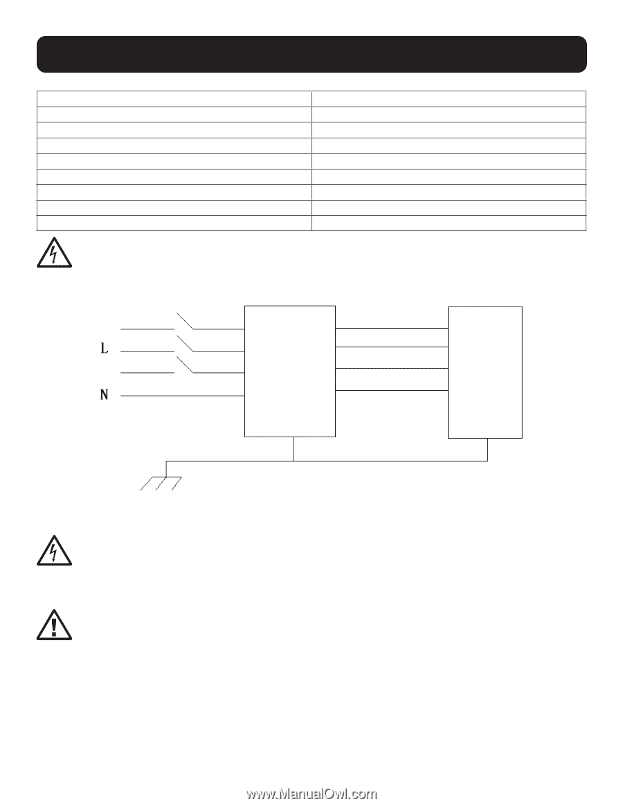
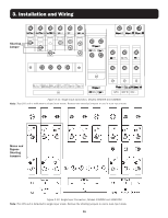
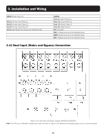
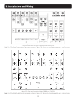
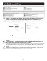
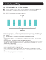
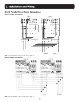
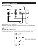
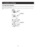
3. Installation and Wiring Mains Primary input Line Bypass Secondary/Bypass input line (optional) Vin-L1: Primary input Phase L1 Vin-L2: Primary input Phase L2 Vin-L3: Primary input Phase L3 Vin-N: Input Neutral for primary and secondary input BPS-L1: Secondary input Phase L1 BPS-L2: Secondary input Phase L2 BPS-L3: Secondary input Phase L3 Output Vout-L1: Output Phase L1 Vout-L2: Output Phase L2 Vout-L3: Output Phase L3 Vout-N: Output Neutral PE: Grounding BAT+: Positive terminal of the batteries string BATN: Battery Center Tap N BAT-: Negative terminal of the batteries string WARNING: In the case of dual input operation, ensure the copper wire between each input line has been removed. The AC input and the AC bypass supplies must be referenced to the same neutral point. Choose the appropriate power cable (refer to Table 3.1). The diameter of the connection terminal of the cable should be greater than or equal to that of the connection poles. Input L1 (A) Input L2 (B) Input L3 (C) Input N UPS Output L1 (A) Output L2 (B) Output L3 (C) Output N Load Figure 3-16: Input and Output Connections WARNING! If the load equipment is not ready to accept power upon the arrival of the commissioning engineer, then ensure that the system output cables are safely isolated at their ends. Connect the safety earth and any necessary bonding earth cables to the copper earth screw located on the floor of the equipment below the power connections. All cabinets in the UPS must be grounded properly. CAUTION! Installation and wiring must be performed in accordance with local codes/regulations and installed using the following instructions by a qualified electrical service technician only. 31
-
 1
1 -
2
-
3
-
4
-
5
-
6
-
7
-
8
-
9
-
10
-
11
-
12
-
13
-
14
-
15
-
16
-
17
-
18
-
19
-
20
-
21
-
22
-
23
-
24
-
25
-
 26
26 -
 27
27 -
 28
28 -
 29
29 -
 30
30 -
 31
31 -
 32
32 -
 33
33 -
 34
34 -
 35
35 -
 36
36 -
37
-
38
-
39
-
40
-
41
-
42
-
43
-
44
-
45
-
46
-
47
-
48
-
49
-
50
-
51
-
52
-
53
-
54
-
55
-
56
-
57
-
58
-
59
-
60
-
61
-
62
-
63
-
64
-
65
-
66
-
67
-
68
-
69
-
70
-
71
-
72
-
73
-
74
-
75
-
76
-
77
-
78
-
79
-
80
-
81
-
82
-
83
-
84
-
85
-
86
-
87
-
88
-
89
-
90
-
91
-
92
-
93
-
94
-
95
-
96
-
97
-
98
-
99
-
100
-
101
-
102
-
103
-
104
-
105
-
106
-
107
-
108
-
109
-
110
-
111
-
112
-
113
-
114
-
115
-
116
-
117
-
118
-
119
-
120
-
121
-
122
-
123
-
124
-
125
-
126
-
127
-
128
-
129
-
130
-
131
-
132
-
133
-
134
-
135
-
136
-
137
-
138
-
139
-
140
-
141
-
142
-
143
-
144
-
145
-
146
-
147
-
148
-
149
-
150
-
151
-
152
-
153
-
154
-
155
-
156
-
157
-
158
-
159
-
160
-
161
-
162
-
163
-
164
-
165
-
166
-
167
-
168
-
169
-
170
-
171
-
172
-
173
-
174
-
175
-
176
-
177
-
178
-
179
-
180
-
181
-
182
-
183
-
184
-
185
-
186
-
187
-
188
-
189
-
190
-
191
-
192
-
193
-
194
-
195
-
196
-
197
-
198
-
199
-
200
-
201
-
202
-
203
-
204
-
205
-
206
-
207
-
208
-
209
-
210
-
211
-
212
-
213
-
214
-
215
-
216
-
217
-
218
-
219
-
220
-
221
-
222
-
223
-
224
-
225
-
226
-
227
-
228
-
229
-
230
-
231
-
232
-
233
-
234
-
235
-
236
-
237
-
238
-
239
-
240
-
241
-
242
-
243
-
244
-
245
-
246
-
247
-
248
 |
 |