Tripp Lite S3M60K60K6T Owners Manual S3M 3-Phase UPS Systems for Models S3M25- - Page 32
UPS Installation for Parallel Systems
 |
View all Tripp Lite S3M60K60K6T manuals
Add to My Manuals
Save this manual to your list of manuals |
Page 32 highlights
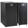
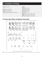
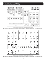
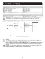
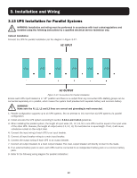
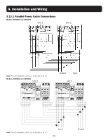
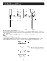
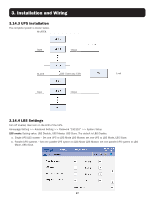
3. Installation and Wiring 3.13 UPS Installation for Parallel Systems WARNING: Installation and wiring must be performed in accordance with local codes/regulations and installed using the following instructions by a qualified electrical service technician only. Cabinet Installation Connect the UPS for parallel installation per the diagram in Figure 3-17. AC INPUT UPS1 UPS2 UPS3 UPS4 UPS5 UPS6 AC OUTPUT Figure 3-17: Connections for Parallel Installation Ensure each UPS input breaker is in "off" position and there is no output from any connected UPS. Battery groups can be connected separately or in parallel, which means the system itself provides both separate battery and common battery. WARNING! Make sure the N, L1, L2 and L3 lines are correct and grounding is well connected. 1. Parallel configuration supports up to six UPS systems. Do not attempt to link more than six UPS systems via parallel configuration. 2. Install and wire the UPS system according to section 3.13.1 and 3.13.2 guidelines. 3. When installing the parallel system, the length of input wires (L1, L2, L3, N) in one UPS must be equal to the input wires of the other UPS. Likewise, the length of output wires (L1, L2, L3, N) must also be in equal length. If not, it will cause unbalance current on the output load. 4. Connect the input wiring of each UPS to an input breaker. 5. Connect all input breaker wiring to a main input breaker. 6. Connect the output wiring of each UPS to an output breaker. 7. Connect all output breakers to a main output breaker. This main output breaker will directly connect to the loads. 8. If an external battery pack is used, each UPS must be connected to an independent battery pack or a common battery pack. 9. Refer to the following wiring diagram for parallel installation: 32
-
 1
1 -
2
-
3
-
4
-
5
-
6
-
7
-
8
-
9
-
10
-
11
-
12
-
13
-
14
-
15
-
16
-
17
-
18
-
19
-
20
-
21
-
22
-
23
-
24
-
25
-
26
-
 27
27 -
 28
28 -
 29
29 -
 30
30 -
 31
31 -
 32
32 -
 33
33 -
 34
34 -
 35
35 -
 36
36 -
 37
37 -
38
-
39
-
40
-
41
-
42
-
43
-
44
-
45
-
46
-
47
-
48
-
49
-
50
-
51
-
52
-
53
-
54
-
55
-
56
-
57
-
58
-
59
-
60
-
61
-
62
-
63
-
64
-
65
-
66
-
67
-
68
-
69
-
70
-
71
-
72
-
73
-
74
-
75
-
76
-
77
-
78
-
79
-
80
-
81
-
82
-
83
-
84
-
85
-
86
-
87
-
88
-
89
-
90
-
91
-
92
-
93
-
94
-
95
-
96
-
97
-
98
-
99
-
100
-
101
-
102
-
103
-
104
-
105
-
106
-
107
-
108
-
109
-
110
-
111
-
112
-
113
-
114
-
115
-
116
-
117
-
118
-
119
-
120
-
121
-
122
-
123
-
124
-
125
-
126
-
127
-
128
-
129
-
130
-
131
-
132
-
133
-
134
-
135
-
136
-
137
-
138
-
139
-
140
-
141
-
142
-
143
-
144
-
145
-
146
-
147
-
148
-
149
-
150
-
151
-
152
-
153
-
154
-
155
-
156
-
157
-
158
-
159
-
160
-
161
-
162
-
163
-
164
-
165
-
166
-
167
-
168
-
169
-
170
-
171
-
172
-
173
-
174
-
175
-
176
-
177
-
178
-
179
-
180
-
181
-
182
-
183
-
184
-
185
-
186
-
187
-
188
-
189
-
190
-
191
-
192
-
193
-
194
-
195
-
196
-
197
-
198
-
199
-
200
-
201
-
202
-
203
-
204
-
205
-
206
-
207
-
208
-
209
-
210
-
211
-
212
-
213
-
214
-
215
-
216
-
217
-
218
-
219
-
220
-
221
-
222
-
223
-
224
-
225
-
226
-
227
-
228
-
229
-
230
-
231
-
232
-
233
-
234
-
235
-
236
-
237
-
238
-
239
-
240
-
241
-
242
-
243
-
244
-
245
-
246
-
247
-
248
 |
 |