Tripp Lite SV20KM1P1B Owners Manual for SmartOnline 208V SV-Series 3-Phase Mod - Page 13
Installation
 |
View all Tripp Lite SV20KM1P1B manuals
Add to My Manuals
Save this manual to your list of manuals |
Page 13 highlights
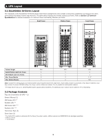
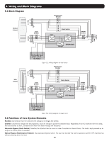
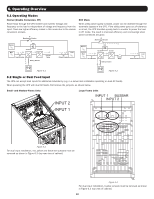
7. Installation 7.1 Breakers and Wiring Terminal Block The input breaker, maintenance bypass breaker and output breaker are located at the front of the Switch Module of the UPS system. The battery breaker and input/output wiring terminal blocks are at the rear of the Switch Module. To access the terminals from the back of the UPS, remove the protective Plexiglas® panel cover. Wiring installation must be made from the top of the UPS cabinet using the two terminal conduit covers provided. For connection details, refer to Figure 7.1 (large-frame terminal block shown). Figure 7.1 Function Output Block Connection to the supported load Alternate Input Block (Input 2) Alternate AC input source connection Main Input Block (Input 1) Primary AC input source connection Grounding Terminal For UPS grounding Battery Input Block For external battery connection Description Includes R (L1), S (L2), T (L3) and Neutral terminals Includes R (L1), S (L2), T (L3) and Neutral terminals Includes R (L1), S (L2), T (L3) and Neutral terminals Includes one grounding terminal Includes Positive (+), Negative (-) and Neutral (N) terminals 7.2 STS Module Installation The STS Module and Switch Module are pre-installed in the frame. STS Module comprises: • Control Circuit • Power Circuit • Communication Circuit (including SNMP, Serial [RS-232]) • Internal Static Transfer Switch • Breaker(s) Power and Battery Modules can be added according to the user's requirements. The tables on the following page indicate the maximum current and cable configurations per assembly. Note: Internal battery modules for Small- and Medium-Frame systems only. 13
-
 1
1 -
2
-
3
-
4
-
5
-
6
-
7
-
 8
8 -
 9
9 -
 10
10 -
 11
11 -
 12
12 -
 13
13 -
 14
14 -
 15
15 -
 16
16 -
 17
17 -
 18
18 -
19
-
20
-
21
-
22
-
23
-
24
-
25
-
26
-
27
-
28
-
29
-
30
-
31
-
32
-
33
-
34
-
35
-
36
-
37
-
38
-
39
-
40
-
41
-
42
-
43
-
44
-
45
-
46
-
47
-
48
-
49
-
50
-
51
-
52
-
53
-
54
-
55
-
56
-
57
-
58
-
59
-
60
-
61
-
62
-
63
-
64
-
65
-
66
-
67
-
68
-
69
-
70
-
71
-
72
-
73
-
74
-
75
-
76
-
77
-
78
-
79
-
80
-
81
-
82
-
83
-
84
-
85
-
86
-
87
-
88
-
89
-
90
-
91
-
92
-
93
-
94
-
95
-
96
-
97
-
98
-
99
-
100
-
101
-
102
-
103
-
104
-
105
-
106
-
107
-
108
-
109
-
110
-
111
-
112
 |
 |
