Tripp Lite SV20KM1P1B Owners Manual for SmartOnline 208V SV-Series 3-Phase Mod - Page 15
Installing a Power Module
 |
View all Tripp Lite SV20KM1P1B manuals
Add to My Manuals
Save this manual to your list of manuals |
Page 15 highlights
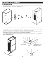
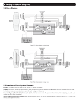
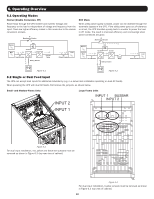
7. Installation 7.2.1 Installing a Power Module WARNING: Ensure all Power Modules contain identical firmware versions prior to installation. Each Power Module capacity is 20kVA/18kW and comprises: • Power Factor Correction Rectifier • Battery Charger • Inverter • Control Circuit Figure 7.2 The hot-swappable Power Module allows for quick maintenance and system expansion. A latch located at the front of each module fixes and locks the module in its assigned slot. To install the Power Module, follow the procedure below. 1. Using the DIP switch on the front panel of each Power Module, set the module ID (0-7). The module ID should be exclusive per module. Note: The default position is 0 for all DIP switches. Module ID Module DIP Switch 0 POWER 1 POWER 2 POWER 3 POWER 4 POWER 5 POWER 6 POWER 7 POWER Table 7.1 2. Place the ready switch on the front panel of the Power Module in the unlocked position by rotating the knob counterclockwise. 3. Remove blanking panel and insert Power Module into its identified frame position and slide into cabinet (retain the four screws to install Power Module in step 4). 15
-
 1
1 -
2
-
3
-
4
-
5
-
6
-
7
-
8
-
9
-
 10
10 -
 11
11 -
 12
12 -
 13
13 -
 14
14 -
 15
15 -
 16
16 -
 17
17 -
 18
18 -
 19
19 -
 20
20 -
21
-
22
-
23
-
24
-
25
-
26
-
27
-
28
-
29
-
30
-
31
-
32
-
33
-
34
-
35
-
36
-
37
-
38
-
39
-
40
-
41
-
42
-
43
-
44
-
45
-
46
-
47
-
48
-
49
-
50
-
51
-
52
-
53
-
54
-
55
-
56
-
57
-
58
-
59
-
60
-
61
-
62
-
63
-
64
-
65
-
66
-
67
-
68
-
69
-
70
-
71
-
72
-
73
-
74
-
75
-
76
-
77
-
78
-
79
-
80
-
81
-
82
-
83
-
84
-
85
-
86
-
87
-
88
-
89
-
90
-
91
-
92
-
93
-
94
-
95
-
96
-
97
-
98
-
99
-
100
-
101
-
102
-
103
-
104
-
105
-
106
-
107
-
108
-
109
-
110
-
111
-
112
 |
 |
