Tripp Lite SV20KM1P1B Owners Manual for SmartOnline 208V SV-Series 3-Phase Mod - Page 17
Cold Start
 |
View all Tripp Lite SV20KM1P1B manuals
Add to My Manuals
Save this manual to your list of manuals |
Page 17 highlights
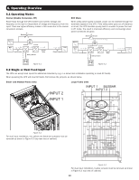
7. Installation 7.2.5 External Battery Cabinet Connection Once the battery installation is completed, ensure the corrected nominal battery voltage (+/- 120V DC), battery capacity and maximum charging current data is programmed into the LCD settings. If the actual installation settings differ from the default settings in the LCD, the UPS alarm may sound continuously. See Section 9.3.6.3: Battery for details. External battery cabinet External battery cabinet Back panel of Switch Unit +N+N- External Battery Input/Output Breaker and Disconnect Figure 7.4 Once all modules are assembled and installation cabling is complete, switch the UPS main breaker on the front of the UPS to "On". The UPS system is now on bypass. Enter the Controls Screen on the Control Panel to place the UPS system in full operation. See Section 9.3.4 Control Screen for details. 7.3 Cold Start Start Up of the UPS System should be undertaken via the Control Panel. It is possible to start the UPS without an AC input via the "Cold Start" button on the Power Module: 1. Press the "Cold Start" button as shown in the figure below. Cold Start Button POWER Figure 7.5 2. The UPS will enter standby mode. Immediately press the "Power On/Off" button and hold for 2 seconds, and the UPS will enter Battery Mode. The Inverter and Battery LEDs will be illuminated. Cold Start procedure is complete. If more than one Power Module is installed in the frame, performing the cold start procedure on one will translate to all other Power Modules installed automatically. Note: The UPS system will function correctly upon initial startup. However, maximum system battery runtime will be available only after the UPS system has been charged for approximately 24 hours. 17
-
 1
1 -
2
-
3
-
4
-
5
-
6
-
7
-
8
-
9
-
10
-
11
-
 12
12 -
 13
13 -
 14
14 -
 15
15 -
 16
16 -
 17
17 -
 18
18 -
 19
19 -
 20
20 -
 21
21 -
 22
22 -
23
-
24
-
25
-
26
-
27
-
28
-
29
-
30
-
31
-
32
-
33
-
34
-
35
-
36
-
37
-
38
-
39
-
40
-
41
-
42
-
43
-
44
-
45
-
46
-
47
-
48
-
49
-
50
-
51
-
52
-
53
-
54
-
55
-
56
-
57
-
58
-
59
-
60
-
61
-
62
-
63
-
64
-
65
-
66
-
67
-
68
-
69
-
70
-
71
-
72
-
73
-
74
-
75
-
76
-
77
-
78
-
79
-
80
-
81
-
82
-
83
-
84
-
85
-
86
-
87
-
88
-
89
-
90
-
91
-
92
-
93
-
94
-
95
-
96
-
97
-
98
-
99
-
100
-
101
-
102
-
103
-
104
-
105
-
106
-
107
-
108
-
109
-
110
-
111
-
112
 |
 |
