Yamaha RX-V563 Owner's Manual - Page 17
Information on jacks and cable plugs, Audio jacks - osd
 |
UPC - 027108929972
View all Yamaha RX-V563 manuals
Add to My Manuals
Save this manual to your list of manuals |
Page 17 highlights
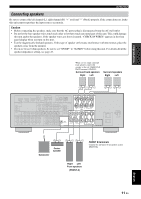
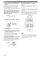
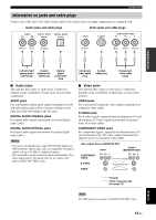
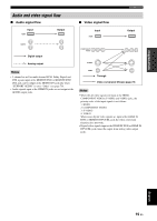
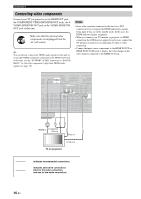
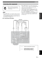
PREPARATION Connections Information on jacks and cable plugs Connect one of the type of the audio jack(s) and/or video jack(s) that your input components are equipped with. Audio jacks and cable plugs Video jacks and cable plugs AUDIO L R DIGITAL AUDIO COAXIAL DIGITAL AUDIO OPTICAL VIDEO S VIDEO COMPONENT VIDEO PR PB Y (White) (Red) (Orange) (Yellow) (Red) (Blue) (Green) L R C O V S PR PB Y Left and right Coaxial analog audio digital audio cable plugs cable plug Optical digital audio cable plug Composite video cable plug S-video cable plug Component video cable plugs ■ Audio jacks This unit has three types of audio jacks. Connection depends on the availability of audio jacks on your other components. AUDIO jacks For conventional analog audio signals transmitted via left and right analog audio cables. Connect red plugs to the right jacks and white plugs to the left jacks. DIGITAL AUDIO COAXIAL jacks For digital audio signals transmitted via coaxial digital audio cables. DIGITAL AUDIO OPTICAL jacks For digital audio signals transmitted via optical digital audio cables. Notes • You can use the digital jacks to input PCM, Dolby Digital and DTS bitstreams. Optical input jacks are compatible with digital signals with up to 96 kHz of sampling frequency. • This unit handles digital and analog signals independently. Thus audio signals input at the digital jacks are not output at the analog AUDIO OUT (REC) jacks. ■ Video jacks This unit has three types of video jacks. Connection depends on the availability of input jacks on your video monitor. VIDEO jacks For conventional composite video signals transmitted via composite video cables. S VIDEO jacks For S-video signals, separated into the luminance (Y) and chrominance (C) video signals transmitted on separate wires of S-video cables. COMPONENT VIDEO jacks For component signals, separated into the luminance (Y) and chrominance (PB, PR) video signals transmitted on separate wires of component video cables. Video signal flow for MONITOR OUT COMPONENT VIDEO Input PR PB Y Output (MONITOR OUT) PR PB Y S VIDEO VIDEO Through Video conversion ON (see page 73) Note The OSD signal is not output at the DVR OUT (REC) jacks. English 13 En
-
 1
1 -
2
-
3
-
4
-
5
-
6
-
7
-
8
-
9
-
10
-
11
-
 12
12 -
 13
13 -
 14
14 -
 15
15 -
 16
16 -
 17
17 -
 18
18 -
 19
19 -
 20
20 -
 21
21 -
 22
22 -
23
-
24
-
25
-
26
-
27
-
28
-
29
-
30
-
31
-
32
-
33
-
34
-
35
-
36
-
37
-
38
-
39
-
40
-
41
-
42
-
43
-
44
-
45
-
46
-
47
-
48
-
49
-
50
-
51
-
52
-
53
-
54
-
55
-
56
-
57
-
58
-
59
-
60
-
61
-
62
-
63
-
64
-
65
-
66
-
67
-
68
-
69
-
70
-
71
-
72
-
73
-
74
-
75
-
76
-
77
-
78
-
79
-
80
-
81
-
82
-
83
-
84
-
85
-
86
-
87
-
88
-
89
-
90
-
91
-
92
-
93
-
94
-
95
-
96
-
97
-
98
-
99
-
100
-
101
-
102
-
103
-
104
-
105
-
106
-
107
-
108
-
109
-
110
-
111
-
112
-
113
-
114
 |
 |
