3Com 3CRWE454G72 User Guide - Page 16
Rear Panel, Wireless Antennae, Power Adapter Socket, Ethernet Port, Reset Button
 |
View all 3Com 3CRWE454G72 manuals
Add to My Manuals
Save this manual to your list of manuals |
Page 16 highlights
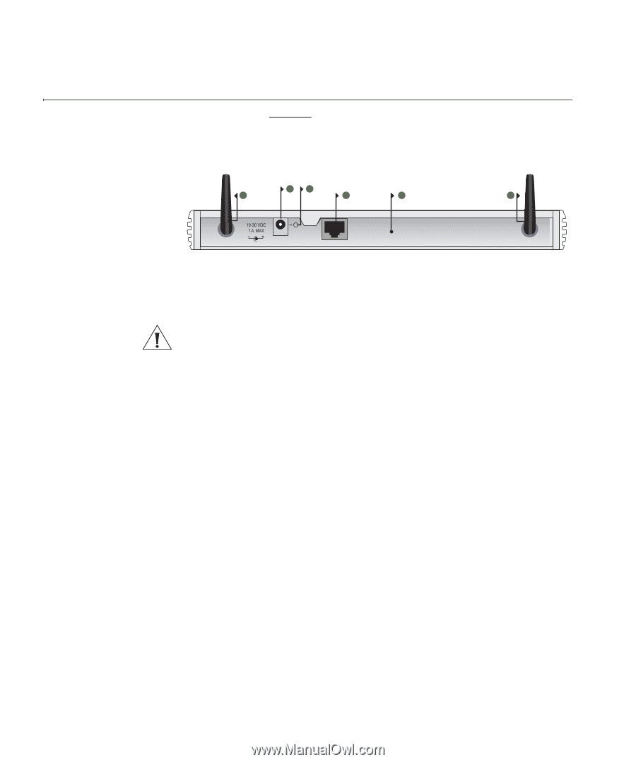
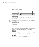
16 CHAPTER 1: INTRODUCING THE ACCESS POINT Rear Panel The rear panel (Figure 3) of the Access Point contains one LAN port, a reset button, a power adapter OK LED and a power adapter socket. Figure 3 Access Point - Rear Panel 6 7 5 8 9 5 OK Ethernet RESET 5 Wireless Antennae The antennae on the product should be placed in a 'V' position when initially installed. CAUTION: Do not force the antennae round further than 90 degrees in either direction. 6 Power Adapter Socket Only use the power adapter supplied with this Access Point. Do not use any other adapter. 7 Power Adapter OK LED Green Indicates that the power adapter is supplying Power to the Access Point. If the LED is off, there may be a problem with the power adapter or adapter cable. 8 Ethernet Port Use the supplied patch cable to connect the Access Point to the LAN. The port will automatically adjust to the correct speed and duplex. 9 Reset Button This button allows you to reset the unit to factory defaults.
-
 1
1 -
2
-
3
-
4
-
5
-
6
-
7
-
8
-
9
-
10
-
 11
11 -
 12
12 -
 13
13 -
 14
14 -
 15
15 -
 16
16 -
 17
17 -
 18
18 -
 19
19 -
 20
20 -
 21
21 -
22
-
23
-
24
-
25
-
26
-
27
-
28
-
29
-
30
-
31
-
32
-
33
-
34
-
35
-
36
-
37
-
38
-
39
-
40
-
41
-
42
-
43
-
44
-
45
-
46
-
47
-
48
-
49
-
50
-
51
-
52
-
53
-
54
-
55
-
56
-
57
-
58
-
59
-
60
-
61
-
62
-
63
-
64
-
65
-
66
-
67
-
68
-
69
-
70
-
71
-
72
-
73
-
74
-
75
-
76
-
77
-
78
-
79
-
80
-
81
-
82
-
83
-
84
-
85
-
86
-
87
-
88
-
89
-
90
-
91
-
92
-
93
-
94
-
95
-
96
-
97
-
98
-
99
-
100
-
101
-
102
 |
 |