Asus CUR-DLS CUR-DLS User Manual - Page 23
H/w Setup
 |
View all Asus CUR-DLS manuals
Add to My Manuals
Save this manual to your list of manuals |
Page 23 highlights
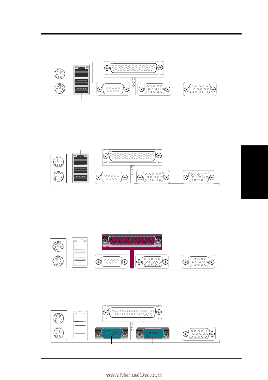
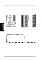
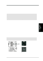
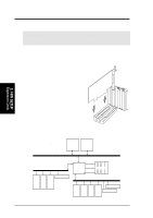
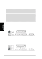
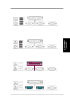
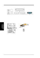
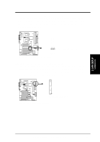
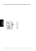
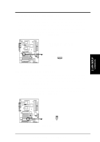
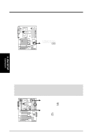
3. HARDWARE SETUP 3) Universal Serial BUS Ports 0 & 1 (Black two 4-pin USB) Two USB ports are available for connecting USB devices. USB 1 Universal Serial Bus (USB) 2 4) Fast-Ethernet Port Connector (RJ45) (optional) The RJ45 connector is optional at the time of purchase and is located on top of the USB connectors. The connector allows the motherboard to connect to a Local Area Network (LAN) through a network hub. RJ45 5) Parallel Port Connector (Burgundy 25-pin PRINTER) You can enable the parallel port and choose the IRQ through Onboard Parallel Port (see 4.4.2 I/O Device Configuration). NOTE: Serial printers must be connected to the serial port. Parallel (Printer) Port (25-pin female) 3. H/W SETUP Connectors 6) Serial Port Connectors (Teal/Turquoise 9-pin COM1/COM2) Two serial ports can be used for pointing devices or other serial devices. See Onboard Serial Port 1 in 4.2.2 I/O Device Configuration for settings. COM 1 COM 2 Serial Ports (9-pin male) ASUS CUR-DLS User's Manual 23
-
 1
1 -
2
-
3
-
4
-
5
-
6
-
7
-
8
-
9
-
10
-
11
-
12
-
13
-
14
-
15
-
16
-
17
-
 18
18 -
 19
19 -
 20
20 -
 21
21 -
 22
22 -
 23
23 -
 24
24 -
 25
25 -
 26
26 -
 27
27 -
 28
28 -
29
-
30
-
31
-
32
-
33
-
34
-
35
-
36
-
37
-
38
-
39
-
40
-
41
-
42
-
43
-
44
-
45
-
46
-
47
-
48
-
49
-
50
-
51
-
52
-
53
-
54
-
55
-
56
-
57
-
58
-
59
-
60
-
61
-
62
-
63
-
64
-
65
-
66
-
67
-
68
-
69
-
70
-
71
-
72
-
73
-
74
-
75
-
76
-
77
-
78
-
79
-
80
-
81
-
82
-
83
-
84
-
85
-
86
-
87
-
88
-
89
-
90
-
91
-
92
-
93
-
94
-
95
-
96
-
97
-
98
-
99
-
100
-
101
-
102
-
103
-
104
-
105
-
106
-
107
-
108
-
109
-
110
 |
 |