Asus CUR-DLS CUR-DLS User Manual - Page 29
ASUS CUR-DLS User's Manual, SMBus Connector 5-1 pin SMB, NIC Activity LED 2-pin, Status LED 2-pin,
 |
View all Asus CUR-DLS manuals
Add to My Manuals
Save this manual to your list of manuals |
Page 29 highlights
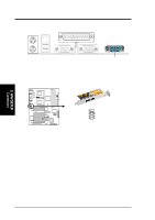
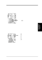
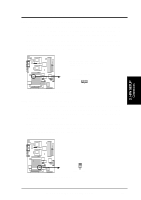
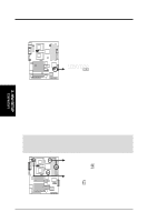
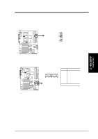
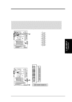
3. HARDWARE SETUP 16) SMBus Connector (5-1 pin SMB) This connector allows you to connect SMBus (System Management Bus) devices. SMBus devices communicate by means of the SMBus with an SMBus host and/or other SMBus devices. SMBus is a specific implementation of an I2C bus, which is a multi-device bus; that is, multiple chips can be connected to the same bus and each one can act as a master by initiating data transfer. R CUR-DLS +5V SMBDATA Ground SMBCLK 1 SMB 3. H/W SETUP Connectors CUR-DLS SMBus Connector The following PANEL illustration is used for items 17-26 (next page). Power LED + NIC activity LED- Power LED - Key GND NMI button +5V HDD access LED+ HDD access LED- Speaker R CUR-DLS Pin Connector 1 & 12 NIC Activity LED 3 & 4 Status LED 11 20 4 & 5 SMI Lead 6 & 7* Power Button 1 10 7* & 8 9 & 10 Chassis Intrusion Reset Switch 11 & 13 Power LED 15* & 16 NMI Button 17 & 20 Speaker 18 & 19 HDD Access LED * Shared NIC activity LED+ Status LED+ Status LED - SMI# buttton/sleep# button GND Power button GND Chassis intrude RESET button GND CUR-DLS System Panel Connectors 17) NIC Activity LED (2-pin) This shows the status of the NIC through a panel-mounted LED. 18) Status LED (2-pin) This shows the system status as programmed through ASUS ASIC. 19) System Management Interrupt Lead (2-pin) This allows the user to manually place the system into a suspend mode or "Green" mode where system activity will be instantly decreased to save electricity and expand the life of certain components when the system is not in use. This 2-pin connector (see the preceding figure) connects to the case-mounted suspend switch. ASUS CUR-DLS User's Manual 29
-
 1
1 -
2
-
3
-
4
-
5
-
6
-
7
-
8
-
9
-
10
-
11
-
12
-
13
-
14
-
15
-
16
-
17
-
18
-
19
-
20
-
21
-
22
-
23
-
 24
24 -
 25
25 -
 26
26 -
 27
27 -
 28
28 -
 29
29 -
 30
30 -
 31
31 -
 32
32 -
 33
33 -
 34
34 -
35
-
36
-
37
-
38
-
39
-
40
-
41
-
42
-
43
-
44
-
45
-
46
-
47
-
48
-
49
-
50
-
51
-
52
-
53
-
54
-
55
-
56
-
57
-
58
-
59
-
60
-
61
-
62
-
63
-
64
-
65
-
66
-
67
-
68
-
69
-
70
-
71
-
72
-
73
-
74
-
75
-
76
-
77
-
78
-
79
-
80
-
81
-
82
-
83
-
84
-
85
-
86
-
87
-
88
-
89
-
90
-
91
-
92
-
93
-
94
-
95
-
96
-
97
-
98
-
99
-
100
-
101
-
102
-
103
-
104
-
105
-
106
-
107
-
108
-
109
-
110
 |
 |
