Asus CUR-DLS CUR-DLS User Manual - Page 24
ASUS CUR-DLS User's Manual, Monitor Output Connector Blue 15-pin VGA, USB Header 10-1 pin USBPORT
 |
View all Asus CUR-DLS manuals
Add to My Manuals
Save this manual to your list of manuals |
Page 24 highlights
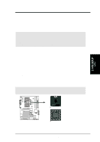
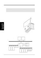
3. HARDWARE SETUP 7) Monitor Output Connector (Blue 15-pin VGA) This connector is for output to a VGA-compatible device. VGA Monitor (15-pin Female) 8) USB Header (10-1 pin USBPORT) If the USB port connectors on the back panel are inadequate, one USB header is available for two additional USB port connectors. Connect the provided USB connector set to the header and mount it to an open slot on your chassis. R CUR-DLS CUR-DLS USB Header 5 NC GND USBP2+ USBP2- USB Power 1 10 GND USBP3+ USBP3- USB Power 6 USBPORT 3. H/W SETUP Connectors 24 ASUS CUR-DLS User's Manual
-
 1
1 -
2
-
3
-
4
-
5
-
6
-
7
-
8
-
9
-
10
-
11
-
12
-
13
-
14
-
15
-
16
-
17
-
18
-
 19
19 -
 20
20 -
 21
21 -
 22
22 -
 23
23 -
 24
24 -
 25
25 -
 26
26 -
 27
27 -
 28
28 -
 29
29 -
30
-
31
-
32
-
33
-
34
-
35
-
36
-
37
-
38
-
39
-
40
-
41
-
42
-
43
-
44
-
45
-
46
-
47
-
48
-
49
-
50
-
51
-
52
-
53
-
54
-
55
-
56
-
57
-
58
-
59
-
60
-
61
-
62
-
63
-
64
-
65
-
66
-
67
-
68
-
69
-
70
-
71
-
72
-
73
-
74
-
75
-
76
-
77
-
78
-
79
-
80
-
81
-
82
-
83
-
84
-
85
-
86
-
87
-
88
-
89
-
90
-
91
-
92
-
93
-
94
-
95
-
96
-
97
-
98
-
99
-
100
-
101
-
102
-
103
-
104
-
105
-
106
-
107
-
108
-
109
-
110
 |
 |
24
ASUS CUR-DLS User’s Manual
3. HARDWARE SETUP
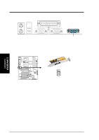
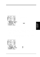
7)
Monitor Output Connector (Blue 15-pin VGA)
This connector is for output to a VGA-compatible device.
VGA Monitor (15-pin Female)
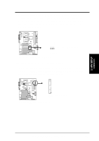
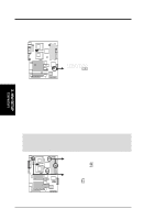
8)
USB Header (10-1 pin USBPORT)
If the USB port connectors on the back panel are inadequate, one USB header is
available for two additional USB port connectors. Connect the provided USB
connector set to the header and mount it to an open slot on your chassis.
CUR-DLS
CUR-DLS USB Header
USBPORT
NC
GND
USBP2+
USBP2–
USB Power
GND
USBP3+
USBP3–
USB Power
1
5
6
10
Connectors
3. H/W SETUP