Asus CUR-DLS CUR-DLS User Manual - Page 25
Chassis Intrusion Lead 4-1 pin CHASSIS Also in Panel Connectors
 |
View all Asus CUR-DLS manuals
Add to My Manuals
Save this manual to your list of manuals |
Page 25 highlights
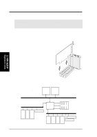
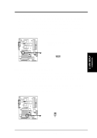
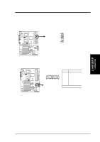
(no connection) Chassis Signal Ground 3. H/W SETUP Connectors 3. HARDWARE SETUP 9) Chassis Intrusion Lead (4-1 pin CHASSIS) Also in Panel Connectors This requires an external detection mechanism such as a chassis intrusion monitor/sensor or microswitch. The sensor is triggered when pins 3 and 4 are opened. If the chassis intrusion lead is not used, a jumper cap must be placed over pins 3 and 4 to close the circuit. R CUR-DLS 1 34 *Same as the "Chassis intrude" lead in the panel connectors CHASSIS CUR-DLS Chassis Open Alarm Lead 10) Floppy Disk Drive Connector (34-1 pin FLOPPY) This connector supports the provided floppy drive ribbon cable. After connecting the single end to the board, connect the two plugs on the other end to the floppy drives. (Pin 5 is removed to prevent inserting in the wrong orientation when using ribbon cables with pin 5 plugged). R CUR-DLS PIN 1 NOTE: Orient the red markings on the floppy ribbon cable to PIN 1. CUR-DLS Floppy Disk Drive Connector ASUS CUR-DLS User's Manual 25
-
 1
1 -
2
-
3
-
4
-
5
-
6
-
7
-
8
-
9
-
10
-
11
-
12
-
13
-
14
-
15
-
16
-
17
-
18
-
19
-
 20
20 -
 21
21 -
 22
22 -
 23
23 -
 24
24 -
 25
25 -
 26
26 -
 27
27 -
 28
28 -
 29
29 -
 30
30 -
31
-
32
-
33
-
34
-
35
-
36
-
37
-
38
-
39
-
40
-
41
-
42
-
43
-
44
-
45
-
46
-
47
-
48
-
49
-
50
-
51
-
52
-
53
-
54
-
55
-
56
-
57
-
58
-
59
-
60
-
61
-
62
-
63
-
64
-
65
-
66
-
67
-
68
-
69
-
70
-
71
-
72
-
73
-
74
-
75
-
76
-
77
-
78
-
79
-
80
-
81
-
82
-
83
-
84
-
85
-
86
-
87
-
88
-
89
-
90
-
91
-
92
-
93
-
94
-
95
-
96
-
97
-
98
-
99
-
100
-
101
-
102
-
103
-
104
-
105
-
106
-
107
-
108
-
109
-
110
 |
 |
