Asus CUR-DLS CUR-DLS User Manual - Page 31
ASUS CUR-DLS User's Manual, ATX Power Supply Connector, pin block ATXPWR, Two 68-pin Ultra160/Ultra2
 |
View all Asus CUR-DLS manuals
Add to My Manuals
Save this manual to your list of manuals |
Page 31 highlights
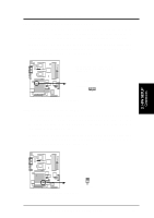
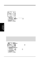
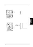
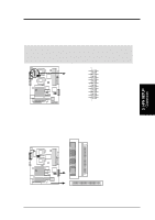
3. H/W SETUP Connectors 3. HARDWARE SETUP 27) ATX Power Supply Connector (20-pin block ATXPWR) This connector connects to an ATX power supply. The plug from the power supply will only insert in one orientation because of the different hole sizes. Find the proper orientation and push down firmly making sure that the pins are aligned. IMPORTANT: Make sure that your ATX power supply can supply at least 10mA on the +5-volt standby lead (+5VSB). You may experience difficulty in powering ON your system if your power supply cannot support the load. For WakeOn-LAN support, your ATX power supply must supply at least 720mA +5VSB. +3.3 Volts +3.3 Volts R CUR-DLS -12.0 Volts Ground +3.3 Volts Ground Power Supply On +5.0 Volts Ground Ground Ground +5.0 Volts Ground Ground -5.0 Volts Power Good +5.0 Volts +5V Standby +5.0 Volts +12.0 Volts CUR-DLS ATX Power Connector 28) Two 68-pin Ultra160/Ultra2 SCSI Connectors This motherboard has two 68-Pin Ultra160/Ultra2 (depending on model) SCSI connectors; one for each of the two channels. Each channel can support a maximum of 15 devices as specified by Ultra160/Ultra2 standards. 1 35 R CUR-DLS SCSI-A 68-Pin Ultra160/ Ultra2-Wide SCSI Connector 34 68 34 68 1 35 SCSI-B 68-Pin Ultra160/Ultra2-Wide SCSI Connector CUR-DLS Onboard SCSI Connectors ASUS CUR-DLS User's Manual 31
-
 1
1 -
2
-
3
-
4
-
5
-
6
-
7
-
8
-
9
-
10
-
11
-
12
-
13
-
14
-
15
-
16
-
17
-
18
-
19
-
20
-
21
-
22
-
23
-
24
-
25
-
 26
26 -
 27
27 -
 28
28 -
 29
29 -
 30
30 -
 31
31 -
 32
32 -
 33
33 -
 34
34 -
 35
35 -
 36
36 -
37
-
38
-
39
-
40
-
41
-
42
-
43
-
44
-
45
-
46
-
47
-
48
-
49
-
50
-
51
-
52
-
53
-
54
-
55
-
56
-
57
-
58
-
59
-
60
-
61
-
62
-
63
-
64
-
65
-
66
-
67
-
68
-
69
-
70
-
71
-
72
-
73
-
74
-
75
-
76
-
77
-
78
-
79
-
80
-
81
-
82
-
83
-
84
-
85
-
86
-
87
-
88
-
89
-
90
-
91
-
92
-
93
-
94
-
95
-
96
-
97
-
98
-
99
-
100
-
101
-
102
-
103
-
104
-
105
-
106
-
107
-
108
-
109
-
110
 |
 |
