Brother International KE-436C Instruction Manual - English - Page 10
Installing the control box
 |
View all Brother International KE-436C manuals
Add to My Manuals
Save this manual to your list of manuals |
Page 10 highlights
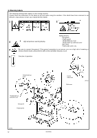
3. INSTALLATION 3-2. Installing the control box Check that the IM sticker is attached to the side of the control box (in the position shown in the illustration). (KE series machine heads can only be used with control boxes which have the IM sticker attached.) Spacers Flat washers Nuts 2454Q 1. Remove the 12 screws (1), and then open the covers (panel mounting assembly (2) and main P.C. board mounting plate (3)). Note: When opening the cover, hold it securely so that it does not fall down. 2. Install the control box with the four accessory bolts (4), spacers (5), flat washers (6) and nuts (7) as shown in the illustration above. * Use two nuts (7) at each installation location, and make sure that both nuts are tightened. 3. Close the covers (panel mounting assembly (2) and main P.C. board mounting plate (3)), and tighten them with the screws (1). * The main P.C. board mounting plate (3) will be opened again during "3-13. Connecting the cords", so provisionally tighten it with the screw (1). 4. Install the power switch (8) with the two screws (9). 5. Secure the power switch cord with the three staples (10). KE-436C 4
-
 1
1 -
2
-
3
-
4
-
 5
5 -
 6
6 -
 7
7 -
 8
8 -
 9
9 -
 10
10 -
 11
11 -
 12
12 -
 13
13 -
 14
14 -
 15
15 -
16
-
17
-
18
-
19
-
20
-
21
-
22
-
23
-
24
-
25
-
26
-
27
-
28
-
29
-
30
-
31
-
32
-
33
-
34
-
35
-
36
-
37
-
38
-
39
-
40
-
41
-
42
-
43
-
44
-
45
-
46
-
47
-
48
-
49
-
50
-
51
-
52
-
53
-
54
-
55
-
56
-
57
-
58
-
59
-
60
-
61
-
62
-
63
-
64
-
65
-
66
-
67
-
68
-
69
-
70
-
71
-
72
-
73
 |
 |
