Casio QT 6000 Service Manual
Casio QT 6000 - 32 MB RAM Manual
 |
View all Casio QT 6000 manuals
Add to My Manuals
Save this manual to your list of manuals |
Casio QT 6000 manual content summary:
- Casio QT 6000 | Service Manual - Page 1
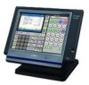
SERVICE MANUAL (without price) ELECTRONIC CASH REGISTER QT-6000 (EX-820) AUG. 2004 INDEX QT-6000 Ver.1 : Sep. 2004 - Casio QT 6000 | Service Manual - Page 2
12-hours before installation or after a long-time vacation (over 30 days). • Before installation, initialize the terminal and leave it turn on over 12-hours. • After a long-time vacation, initialize the terminal and restore the program data if the terminal is in malfunction, and leave it turn on - Casio QT 6000 | Service Manual - Page 3
1.1A 0.25A 1.1A 0.15A 1.1A 0.14A In operation Display off 0.9A 0.5A 0.9A 0.5A 0.9A 0.5A • Memory protection Back-up battery • Clock & Calendar Back-up period Battery life Recharge time Accuracy Auto calendar NiMH (nickel-metal-hydride) HHR-21HL3G1B (USA only - Casio QT 6000 | Service Manual - Page 4
Interface Colors • Touch Panel Name Size • Panel brightness control • Speaker • Microphone • Power supply • Cleck key NL8060BC31-27 12 Ethernet 10BASE-T/100BASE-TX) x 1 PC CARD slot x 1 CF CARD slot x 1 Drawer port x 2 External speaker jack x 1 (ø3.5 mono) External microphone jack x 1 (ø3.5 - Casio QT 6000 | Service Manual - Page 5
CASIO sales options DEVICE NAME MODEL • Magnet i-Button QT-6011DLS • Display set for customer QT-6060D • Display cable for customer QT-6061CB (for mounting to the base) • Display 5-meter cable for customer QT Com2 port only 1-7. Drawer Type M M M M M M L L Drawer Name DL-2785 DL-2786 - Casio QT 6000 | Service Manual - Page 6
core two times. The ferrite core is packed with QT-6000. CAUTION Danger of explosion if battery is incorrectly replaced. Replace only with the same or equivalent type recommended by the manufacturer. Dispose of used batteries according to the manufacture's instructions. VORSICHT ! Explosionsgefahr - Casio QT 6000 | Service Manual - Page 7
Wireless LAN card. Operation: 5. Turn on all peripheral devices of a terminal. 6. Turn on this terminal with pressing the initialize switch and release. Init Sw Copyright(C) 2004 CASIO COMPUTER CO.,LTD. All rights reserved. ROM VER. xxxxxx xxxx CREATE xxxx-xx-xx xx:xx QT-6000 Version x.xx APL - Casio QT 6000 | Service Manual - Page 8
) / All PGM (program only) --- Select the machine to send the data. Note: In case of using wireless inline, we recommend that you should change the ESS ID / WEP KEY character for your security. 2-1-2. How to initialize the terminal (add / replace one terminal) Preparation: 1. All peripheral - Casio QT 6000 | Service Manual - Page 9
" and press key and enter "8888888888" and key to Init 2. 2-2. SYSTEM INITIALIZATION In this chapter shows how to install QT-6000 systems and peripherals. 2-2-1. How to load IPL (Initial Program Loading) Normally, IPL is not necessary since the terminal has efficient programmable options - Casio QT 6000 | Service Manual - Page 10
3. Press the key to proceed, in case of downloading via inline, automatic ID definition is made by this timing. So press the key terminal by terminal. (using COM PORT) xxxxxxx xxxxxxx xxxxxxx xxxxxxx xxxxxxx START CANCEL 4. After finishing IPL, machine initialization is necessary - Casio QT 6000 | Service Manual - Page 11
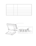
3. DISASSEMBLY s QT-6000 1. Separate the main unit and the stand. 2. Remove one screw and the cover. 3. Remove two screws and the cover. Screws 4. Remove ten screws. Screw × 10 5. Remove one screw and the lid of the software key. 6. Remove the wiring for the DRAWER (a cable and an earth). - 9 - Casio QT 6000 | Service Manual - Page 12
7. Open the CARD SLOT COVER. 8. Remove each screw, and then the PC CARD and the COVER for the CF CARD. CARD SLOT COVER Screws 9. Release the hook and remove the REAR CASE. Be careful with the REAR CASE when removing it since there is a wiring which connects to the speaker. 10. Remove the connector - Casio QT 6000 | Service Manual - Page 13
14. Remove the connector for the battery and the battery. 15. Remove four connectors. Connectors × 4 15. Remove twelve screws and the metal bracket. Screw × 3 Screw × 3 Screw × 3 16. Remove three connectors and one FPC. FPC Connectors × 3 Screw × 3 - 11 - - Casio QT 6000 | Service Manual - Page 14
LCD unit. Screw × 14 19. Remove two screws, one connector and the inverter PCB. Screw × 2 Connectors 20. Remove four screws and the LCD. Screw × 4 The touch panel is fixed by double-sided tape. - 12 - - Casio QT 6000 | Service Manual - Page 15
s QT-6060D 1. Remove four screws. 2. Release the connector and remove the IO PCB. Screw × 4 Connector 3. Remove four screws and separate the unit as shown below. Screw × 4 4. Remove the cap. 5. Remove four screws under both packing. Screw × 2 Screw × 2 - 13 - - Casio QT 6000 | Service Manual - Page 16
6. Release the hook and remove the REAR CASE. 7. Remove five screws, connector and the HINGE. Screw × 5 8. Remove seven screws and separate the LCD Unit. Screw × 7 - 14 - - Casio QT 6000 | Service Manual - Page 17
4. ASSEMBLY s QT-6000 1. Place the LCD UNIT in the frame and fix it with four screws. 2. Connect the connector and fix the inverter PCB with two screws. Screw × 2 3. - Casio QT 6000 | Service Manual - Page 18
5. Connect one PFC and three connector. Terminal side 6. Fix the iron plate with twelve screws. Screw × 3 Screw × 3 Connectors × 3 Screw × 3 7. Connect four connectors. 15. Remove four connectors. Connectors × 4 Screw × 3 - 16 - - Casio QT 6000 | Service Manual - Page 19
8. Connect the connector for the battery and assemble the battery. 9. Assemble the IO Unit and fix it with three screws. Connect four connectors and one FPC. Screw × 3 Connectors 10. Fix the iron plate with four screws. Screw × 4 FPC - 17 - - Casio QT 6000 | Service Manual - Page 20
fix it with ten screws. 12. Fix the PC CARD and the CF CARD COVER. Fix the backup battery cover with one screw. Connect the DRAWER wiring (a cable and an earth). CARD SLOT COVER Screw × 10 Screws 13. Fix the case with two screws. 14. Fix the IP PORT COVER and - Casio QT 6000 | Service Manual - Page 21
s QT-6060D 1. Assemble the LCD Unit in the FRONT CASE with seven screws. Screw × 7 2. Connect the connector and fix the HINGE with five screws. Screw × 5 3. After - Casio QT 6000 | Service Manual - Page 22
5. Fix the cap to the LCD Unit. Be careful with the position of the screw holes. 6. Fix the cap to the stand. Be careful with the direction of the cap. The height of the screw hole on the front side should be lower. 7. Let the connector through the cap and fix the LCD unit with four screws. Screw - Casio QT 6000 | Service Manual - Page 23
5. OPTION INSTALLATION 5-1. Installing the display set for customer (EX-DP-UNIT-16) Metal bracket for type A Metal bracket for type B s There are two types for the display set for customer (EX-DP-UNIT-16). Type A Type B s To install Type A 1. Remove two screws at the bottom and then the cover. 2. - Casio QT 6000 | Service Manual - Page 24
5. Fix EX-DP-UNIT-16 to the main unit with four screws. 6. Connect the cable to the main unit (COM1). 7. Fix the metal bracket which was removed in the above step 2. s To install Type B 1. Remove five screws at the bottom and then the metal bracket. 2. Fix the metal bracket for type B to the main - Casio QT 6000 | Service Manual - Page 25
s LONG POLE It is possible to attach the long pole in QT-6060D. Please arrange the following parts at your side when you need them. Status in 4 Attachment parts (arranged by dealers) LONG-POLE (arranged by dealers) 1 Turn the DP-UNIT-16 over. 2 Remove four pan-head screws which are fixed in STD-POLE - Casio QT 6000 | Service Manual - Page 26
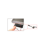
1. Remove the REAR COVER for QT-6000 (No.1 to No.10 in the disassembly procedure). 2. Remove one screw and then the I-Button cover. 3. Insert the I-Button. Ǟ Fix it with a nut. Ǟ Insert the earth plate. Ǟ Fix it with a nut. 4. Assemble the lead wire (earth) into the connector. 5. Wind the lead - Casio QT 6000 | Service Manual - Page 27
6. Store the core in the main unit, and then fix it with fabric tape. 5-3. To install the MCR 1. Remove the REAR COVER for QT-6000 (No.1 to No.10 in the disassembly procedure). 2. Remove the packing from the main unit. 3. Insert the MCR into the special metal bracket. NOTE: Be - Casio QT 6000 | Service Manual - Page 28
QT-6000 with two screws. 6. Connect the connector to QT-6000 drawer connector (three color lead on drawer) to the terminal. 2. Connect frame drawer connector (green lead on drawer) to the terminal. Mount the cash register. 1. Screw in 2 fixing screws bottom side of the terminal. 2. Mount the terminal - Casio QT 6000 | Service Manual - Page 29
x 4P Not shielded wire Twist pair cable • 100BASE-TX Max.100m Max.100m Max.100m Maximum 32 terminals Max.500m Maximum 32 terminals Max.300m 6-2. Wireless LAN There is a PC CARD SLOT in QT-6000 and a wireless LAN CARD can be installed to the PC CARD SLOT. The specifications are as shown below - Casio QT 6000 | Service Manual - Page 30
1 Connection layout Note: Maximum 3 remote printers in the 1 terminal system, 6 remote printers / 2 terminal system, 8 remote printers in the 3 ~ 32 terminal can be defined. PC on-line 2 PC Cable wiring Maximum 32 terminals QT-6000 (Com1) Pin No. Signal name 3 SD/TXD 2 RD/RXD 7 RS/RTS - Casio QT 6000 | Service Manual - Page 31
Release the switch when the display shown below appears. * Operation is not guaranteed if the switch is released before the display appears. Copyright(C)2004 CASIO COMPUTER CO.,LTD. All rights reserved. ROM VER xxxxxx xxxx CREATE xxxx-xx-xx xx:xx QT-6000 Version x.xx APL VER. xxxxxx xxxx INIT - Casio QT 6000 | Service Manual - Page 32
input system Input a command according to the following code. XXXXXXn a g d XXXXXX : additional action n : number of times a ) Dallas key Dallas key no. Dallas key 2 Drawer Dallas key no. Open DRW1 CLOSE 0000 DRW2 CLOSE 1234 Register: Characters enlarged 1.5 times (max. 10 digits) Counter - Casio QT 6000 | Service Manual - Page 33
Check item The following test can be checked in the diagnostic test. No Device to be checked Operation Note 1 Batch test 1 2 Test Device : RAM, FLASH, Display, Print, Time, Drawer 2 Batch test 2 3 Test Device : Display, Back light 3 RAM WRITE/READ test n011 4 RAM READ only test n111 - Casio QT 6000 | Service Manual - Page 34
the wait mode for the input of [OK] or [NG] by the operator after drawer open. (6) Receipt issuance [LCD] *When normally printed BATC H 2 RAM WR OK FLASH CHK SUM OK DATE 01/12/31 TIME 23:59-30 Please Hit Key OK->1 NG->9 DRW ALL OK END 2 [Print] *When normally printed BATC H 2 RAM - Casio QT 6000 | Service Manual - Page 35
] WRITE/READ test for RAM is performed. A counter is displayed for RAM test as follows. [Operation] Operation : n 0 1 1 ST n: 0 = One time check (can be omitted) not 0 = Continuous check (To stop the test, press "ESC" key) [LCD] RAM RAM WR END n011 OK n011 NOTE: Prints the address of the error - Casio QT 6000 | Service Manual - Page 36
you need to perform IPL again after the test. When the memory in the FLASH memory is cleared (by the CLEAR test), the program is cleared also. [Operation] Operation : n 6 1 2 ST n: 0 = One time check (can be omitted) not 0 = Continuous check (To stop the test, press "ESC" key) [LCD] FLASH 612 - Casio QT 6000 | Service Manual - Page 37
ensure the data inside the CF-CARD as well as its performance. [Operation] Operation : p n 0 1 3 ST p : designates PCMCIA SLOT 0 = CF 1 = PCMCIA n: 0 = One time check (can be omitted) not 0 = Continuous check (To stop the test, press "ESC" key) [LCD] CF-CARD CF WR END pn013 OK pn013 NG and the - Casio QT 6000 | Service Manual - Page 38
ensure the data inside the CF-CARD as well as its performance. [Operation] Operation : p n 2 1 3 ST p: designates PCMCIA SLOT 0 = CF 1 = PCMCIA n: 0 = One time check (can be omitted) not 0 = Continuous check (To stop the test, press "ESC" key) [LCD] CF-CARD CF CLR END pn213 OK pn213 NG and the - Casio QT 6000 | Service Manual - Page 39
The display can be switched by the touch of the panel. The display will not change to the next one unless the panel is touched. [Operation] Press [OK] key or [NG] key to end the test when performing one time check. "OK" = 1, "NG" = 9 Operation : n 0 2 1 ST n: 0 = One time check (can be omitted) not - Casio QT 6000 | Service Manual - Page 40
is a test for the LCD backlight. The test ends upon judgment of the operator between [OK] and [NG]. [Operation] Press [OK] key or [NG] key to end the test when performing one time check. "OK" = 1, "NG" = 9 Operation : 1 2 1 ST [LCD] [PRINT] BACK LIGHT 121 BACK LIGHT OK END 121 BACK LIGHT - Casio QT 6000 | Service Manual - Page 41
which turns off upon the end of the test. * When changing the baud rate, make sure to change the REMOTE DISP setting. [Operation] Press [OK] key or [NG] key to end the test when performing one time check. "OK" = 1, "NG" = 9 Operation : b n 0 2 3 ST b: Baud rate selection 0 = 19.2 Kbps, 1 = 9600 bps - Casio QT 6000 | Service Manual - Page 42
. [Operation] Operation : x1 time check (can be omitted) not 0 = Continuous check (To stop the test, press "ESC" key ) d: Printer type selection (1 = RJ, 2 = SLIP) Note that some printers cannot use certain baud rates. Refer to the list below. When changing the baud rate, make sure to change - Casio QT 6000 | Service Manual - Page 43
for RS232C port connection. [Operation] Operation : x n 0 4 d ST x: Baud rate selection 0 = 2400 bps, 1 = 4800 bps, 2 = 9600 bps, 3 = 19.2 kbps, 7 = 115 kbps (COM 1 only) n: 0 = One time check (can be omitted) not 0 = Continuous check (To stop the test, press "ESC" key) d: Port selection 1 = COM1 - Casio QT 6000 | Service Manual - Page 44
connectors to all COM ports. [Operation] Operation : 4 0 ST Baud rate: COM1: 115 kbps, COM 2 - 6 : 9600 bps Check time: one time [LCD] COM BATCH 40 RTS1=1 appears for COM3 to COM6. Note that the actual display shows only a part of the results (not the whole as shown in the left). Figure : - Casio QT 6000 | Service Manual - Page 45
using this ID. When changing the ID. Perform the initialize operation again. b m manually by pressing [ESC] (end the send ECR first.). * About ID ID is effective in the range from 1 through 9. A value which is not in this effective range will be changed to 1, and converted as follows. The upper part - Casio QT 6000 | Service Manual - Page 46
writing the MAC address In the manual input mode, the test enters the wait mode for the input of MAC address. The address can be inputted in 8 bit. Inputting three-digit decimal and the [ST] key determines 8 bits. Performing this operation for 48 bits (6 times) inputs a 48-bit address, and the - Casio QT 6000 | Service Manual - Page 47
unless an error occurs. End the test manually by pressing [ESC] (end the send ECR first.). * About ID ID is effective in the range from 1 through 9. A value which is not in this effective range will be changed to 1, and converted as follows. The upper part of the IP address is fixed as "192 - Casio QT 6000 | Service Manual - Page 48
done one time. * Date and time display Operation : 7 0 ST To stop the operation, press "ESC" key. [LCD] DATE/TIME DATE/TIME END 70 YY/MM/DD HH:MM-SS 70 Each data will be printed only when setting the date and time. [PRINT] DATE/TIME DATE END YYMMDD0170 YY/MM/DD YYMMDD0170 [ 23 ] Drawer open - Casio QT 6000 | Service Manual - Page 49
Buzzer test [Function] This test will check the buzzer function. Ring the one-shot buzzer. [Operation] Operation : n 0 9 2 ST n: 0 = One time check (can be omitted) not 0 = Continuous check (To stop the test, press "ESC" key) [LCD] BUZZ END n092 n092 [PRINT] BUZZ END n092 n092 [ 25 ] OBR test - Casio QT 6000 | Service Manual - Page 50
. The test judges the result between OK and NG by the comparison between already set data and read data. [Operation] Operation : 9 6 ST Press [ESC] key to end the test manually. [LCD] MCR1 indicates track 1 while MCR2 indicates track 2 in the display. * Normally ended (both track 1 and 2) MCR 96 - Casio QT 6000 | Service Manual - Page 51
that the number 8 and 9 automatically are changed to 7. x : 0 → Plays back the sound which was recorded by the command 98. 1 to 9 → Plays back the specific sound. n : 0 → One time check not 0 → Continuous loop (Press [ESC] key to end the test manually.) * In case of one time check only, [OK] and [NG - Casio QT 6000 | Service Manual - Page 52
external microphone. The test records sound for three seconds, followed by the playback of the recorded data at the maximum volume. [Operation] Operation : 9 8 ST Press [OK] or [NG] key to end the test. "OK" = 1 "NG" = 9 [LCD] MIKE 98 MIKE OK END 98 [Print] MIKE 98 MIKE OK END 98 [ 29 - Casio QT 6000 | Service Manual - Page 53
8. CIRCUIT EXPLANATION 8-1. BLOCK DIAGRAM - 51 - Touch Panel MCR Built-in MIC CPU SDRAM BGA90pin FROM LCDC ~6 DSUB9pin x3 SPEAKER Out MIC in SIGNAL ONLY SPEAKER OU MIC in SPEAKER Casio Drawer1 Casio Drawer2 DL-**** DL-**** COM1 DSUB9pin COM2 DSUB9pin COM3 DSUB9pin SIGNAL ONLY +5V Supply - Casio QT 6000 | Service Manual - Page 54
IEEE802.11g LCDC IC (IC45) SVGA TFT PANEL (12.1inch) BUZZER TOUCH PANEL DISPLAY ON/OFF SW SERIAL I/F 3.3V 5V I/O CONTROLLER 78K4 12.5MHz (IC44) DRAWER DRIVE x 2 COMPULSORY SW x 2 LOAD x 2 CLOCK x 2 DATA x 2 INIT SW DRAWER PORT X 2 SOFT WARE KEY DALLAS KEY (OPTION) MCR (OPTION) - 52 - - Casio QT 6000 | Service Manual - Page 55
8-3. RESET CIRCUIT The reset circuit is as follows. 8-4. POWER SUPPLY CIRCUIT 1 VP (DC 19V) For the drawer circuit VOP (DC 5.2V) For the COM2, 3 power and display ON/OFF LED VCC (DC 5V) For the logic circuit power The power supply circuit is as follows. - 53 - - Casio QT 6000 | Service Manual - Page 56
8-5. POWER SUPPLY CIRCUIT 2 VBAT (DC 3.3V) For the battery V1.5 (DC 1.5V) For the CPU core V1.8 (DC 1.8V) For the PCMCIA core The power supply circuit is as follows. 8-6. DRAWER I/F CIRCUIT The drawer open circuit is as follows. - 54 - - Casio QT 6000 | Service Manual - Page 57
8-7. CPU (IC26: SH7751) 8-7-1. Pin Assignment 192 191 190 189 188 187 186 AD0 185 AD1 184 183 182 AD2 181 AD3 180 AD4 179 AD5 178 AD6 177 AD7 176 - Casio QT 6000 | Service Manual - Page 58
Diagram CPU UBC FPU Lower 32-bit data 32-bit address (instructions) 32-bit data (instructions) 32-bit address (data) 32-bit data (load) controller FPU: Floating-point unit INTC: Interrupt controller ITLB: Instruction TLB (translation lookaside buffer) UTLB: Unified TLB (translation lookaside - Casio QT 6000 | Service Manual - Page 59
8-7-3. Pin Function NO. PIN NAME 1 TMS 2 TCK 3 VDDQ 4 VSSQ 5 TDI 6 CSO 7 CS1 8 CS4 9 CS5 10 CS6 11 BS 12 WE0/REG 13 WE1 14 D0 15 VDDQ 16 VSSQ 17 VDD 18 VSS 19 D1 20 D2 21 D3 22 D4 23 D5 24 D6 25 D7 26 D8 27 D9 28 D10 29 VDDQ 30 VSSQ 31 - Casio QT 6000 | Service Manual - Page 60
NO. PIN NAME 55 VDDQ 56 VSSQ 57 A4 58 A5 59 A6 60 A7 61 A8 62 A9 63 A10 64 A11 65 A12 66 A13 67 VDDQ 68 VSSQ 69 A14 70 A15 71 A16 72 A17 73 CAS2/DQM2 74 CAS3/DQM3 75 D16 76 D17 77 D18 78 D19 79 VDDQ 80 VSSQ 81 VDD 82 VSS 83 D20 84 D21 85 - Casio QT 6000 | Service Manual - Page 61
)/mode IO VDD IO GND Bus request (host function)/mode Configuration device select Interrupt (async) Reset output PCI input clock Bus grant (host function)/bus request Bus request (host function)/bus grant System error PCI address/data/port PCI address/data/port IO VDD IO GND I/O PCI address/data - Casio QT 6000 | Service Manual - Page 62
0 Interrupt 1 Interrupt 2 Interrupt 3 I/O GND I/O VDD RTC crystal resonator pin RTC crystal resonator pin RTC VDD RTC GND Hardware standby Reset Reset (H-UDI) Manual reset Nonmaskable interrupt Bus acknowledge/bus request Bus request/bus acknowledge Mode/IOIS16 (PCMCIA) Bus ready SCI data output IO - Casio QT 6000 | Service Manual - Page 63
NO. PIN NAME 219 AUDSYNC 220 AUDCK 221 VDDQ 222 VSSQ 223 AUDATA0 224 AUDATA1 225 VDD 226 VSS 227 AUDATA2 228 AUDATA3 229 Reserved 230 MD3/CE2A 231 MD4/CE2B 232 MD5 233 VDDQ 234 VSSQ 235 DACK0 236 DACK1 237 DRAK0 238 DRAK1 239 VDD 240 VSS 241 STATUS0 242 STATUS1 243 DREQ0 - Casio QT 6000 | Service Manual - Page 64
8-8. I/O CONTROLLER (IC44: uPD784215AGC8018EU) 8-8-1. Pin Assignment P95 P94 P93 P92 P91 P90 TEST/VPP P37/EXA P36/TI01 P122/RTP2 P123/RTP3 P124/RTP4 P125/RTP5 P126/RTP6 P127/RTP7 VDD X2 X1 VSS XT2 XT1 RESET P00/INTP0 P01/INTP1 P02/INTP2/NMI P03/INTP3 P04/INTP4 P05/INTP5 P06/INTP6 AVDD AVREF0 P10/ - Casio QT 6000 | Service Manual - Page 65
ANI0-ANI7 AVREF0 AVDD AVSS P03 PCL BUZ WATCHDOG TIMER REAL-TIME OUTPUT PORT D/A CONVERTER A/D CONVERTER CLOCK OUTPUT CONTROL BUZZER OUTPUT PORT3 PORT4 PORT5 PORT6 PORT7 PORT8 PORT9 PORT10 PORT12 PORT13 SYSTEM CONTROL RxD1/SI1 TxD1/SO1 ASCK1/SCK1 RxD2/SI2 TxD2/ RESET X1 X2 XT1 XT2 VDD VSS - 63 - - Casio QT 6000 | Service Manual - Page 66
SCK0/SCL0 48 P80/A0 49 P81/A1 50 P82/A2 I/O DESCRIPTION IO 8 bit input/output PORT - Power Supply I Main system Clock - GND I Sub system Clock I Reset IO 7 bit input/output PORT - A/D CONVERTER POWER SUPPLY - Application of Standard Voltage for A/D CONVERTER I 8 bit input PORT - Casio QT 6000 | Service Manual - Page 67
PIN NO. PIN NAME 51 P83/A3 52 P84/A4 53 P85/A5 54 P86/A6 55 P87/A7 56 P40/AD0 57 P41/AD1 58 P42/AD2 59 P43/AD3 60 P44/AD4 61 P45/AD5 62 P46/AD6 63 P47/AD7 64 P50/A8 65 P51/A9 66 P52/A10 67 P53/A11 68 P54/A12 69 P55/A13 70 P56/A14 71 P57/A15 72 VSS 73 P60/A16 74 P61/A17 75 - Casio QT 6000 | Service Manual - Page 68
RD 87 WE 88 INT6 89 INT7 90 TVDD 91 RESET 92 RD_WE 93 TESTB 94 U1_CTSB 95 U1_DSRB 96 U1_SIN ADDRESS (A21) I ADDRESS (A22) I IO READ I IO WRITE I INT for ARC I Int for PCMCIA VDD VDD I RESET I READ/WRITE signal I VDD I CST2 I DSR2 I RXD2 O DTR2 O RTS2 O TXD2 I CTS3 I DSR3 I RXD3 - Casio QT 6000 | Service Manual - Page 69
/CAS /WE DQM0 VDD DQ7 VSSQ DQ6 DQ5 VDDQ DQ1 DQ3 VDDQ VDDQ VSSQ DQ4 VDD DQ0 DQ2 CLK CKE Clock Generator Address Mode Register /CS /RAS /CAS /WE Row Address Buffer & Refresh Counter Column Address Buffer & Burst Counter Bank 3 Bank 2 Bank 1 Bank 0 Sense Amplifier Column Decoder & Latch Circuit - Casio QT 6000 | Service Manual - Page 70
WE WP/ACC RY/BY VCC VSS A22 to A0 RESET WE CE OE WP/ACC DQ15 to DQ0 Bank A address Cell Matrix 16 Mbit (Bank A) X-Decoder Bank B Address State Control & Command Register RY/BY Status Control Bank C Address Bank D address X-Decoder Cell Matrix 16 Mbit (Bank D) Y-Gating Y-Gating Y-Gating - Casio QT 6000 | Service Manual - Page 71
8-12. DISPLAY CONTROLLER (IC45: SM712) 8-12-1. Pin Assignment 1 2 3 45 6 7 8 9 10 11 12 13 14 15 16 17 18 19 20 MD12 A MD3 MD4 MD5 MD7 MD31 MD17 MD28 MD20 MD25 MD22 AD0 AD4 - Casio QT 6000 | Service Manual - Page 72
transaction. IDSEL I ID Select. This input is used during PCI configuration read/write cycles. CLK I PCI System Clock, 33 MHz. ~RST PCI System Reset. LynxEM+ asserts this signal to force registers and state machines to initial default I values ~REQ O PCI Bus Request (bus master mode) ~GNT - Casio QT 6000 | Service Manual - Page 73
signal or Display Enable. This signal is used to indicate the active horizontal display time. DE FPR3E [7] is used to select O 1 = M-signal 0 = inactive before any panel voltages or control signals are removed. FPEN is part of the VESA FPDI-1B specification. FPVDDEN O Flat Panel VDD Enable - Casio QT 6000 | Service Manual - Page 74
TVCLK output is used to drive external NTSC/PAL TV encoder. To select NTSC or PAL TV, please refer to CCR65 register General Purpose Registers / I2C USR3 General Purpose register. It is recommended to use USR3 to control TV On/Off. I/O 0 = TV display is OFF 1 = TV display is ON USR2 General - Casio QT 6000 | Service Manual - Page 75
PIN NAME I/O VCC and GROUND Pins HVDD Host Interface VDD on I/O Ring, 3.3V DESCRIPTION MVDD Display Memory Interface VDD on I/O Ring, 3.3V FPVDD Flat Panel Interface VDD on I/O Ring, 3.3V VPVDD VPVDD VPort Interface VDD on I/O Ring 3.3V CVDD Clock (PLL) Analog Power, 3.3V AVDD DAC - Casio QT 6000 | Service Manual - Page 76
8-13. ADPCM SPEECH LSI (IC15: MSM9841) 8-13-1. Pin Assignment D0 1 D1 2 D2 3 D3 4 NC 5 D4 6 D5 7 D6 8 D7 9 NC /ADPCM/PCM Analyzer ADPCM2/ADPCM/PCM/Non-linear PCM Synthesizer DMA I/F Timing Controller DREQL DACKL IOW IOR VCK XT XT RESET - 74 - SG AVDD AGND DVDD DGND ADSD DASD SIOCK TEST0 TEST1 - Casio QT 6000 | Service Manual - Page 77
IOW signals are accepted. When stereo playback is selected, input to DACKL a DMA transfer acknowl- I edge signal for left FIFO memory. Active "L" can be changed to active "H" by command input. If DMA transfer is not used, set this pin to "H" level. IOW Write pulse input pin to write external - Casio QT 6000 | Service Manual - Page 78
PIN NAME XT XT VCK RESET TEST0 TEST1 SG MIN LIN MOUT LOUT AOUTL AOUTR DVDD DGND AVDD AGND I/O DESCRIPTION I O Oscillator connection pins. When external clock is used, input clock into - Casio QT 6000 | Service Manual - Page 79
8-14. ETHERNET CONTROLLER (IC28: LAN91C113) 8-14-1. Pin Assignment 8-14-2. Block Diagram - 77 - - Casio QT 6000 | Service Manual - Page 80
TRDY# STOP# PERR# SERR# PCI Interface PCICLK PCIRST# CLKRUN# GBRST# HWSPND# INTA# IRQ3-IRQ15 RI_OUT#/PME# RESET & Clock Interrupt & Audio PCI Address Decode & Mapping PCI Config. Registers CardBus Address Decode & Mapping ADDR/DATA Buffer PCI to Card Socket A (Func#0) CardBus Interface Master - Casio QT 6000 | Service Manual - Page 81
to its original setting. E003 Wrong operator. Error clerk/Error clerk in check tracking Input correct check number or assign the proper clerk. E005 Insufficient memory. Memory allocation over Reallocate memory. E011 Close the drawer. Drawer compulsory Close cash drawer. E012 Journal paper - Casio QT 6000 | Service Manual - Page 82
and close the check that is occupied. CHECK> key to open a new check currently under the number that different check number. an existing check tracking memory. E052 CHK/TBL No. is Busy. Attempt to use number is being check at that terminal. used in the other terminal. E053 CHK/TBL No. is not - Casio QT 6000 | Service Manual - Page 83
Register item(s) until the balance becomes cannot be finalized. less than zero. positive amount. E080 Electronic Journal Full Electronic journal full Reset the electronic for connection. NO :Remove it from system. ********** CHK M/BM down E107 Both Master&Backup "****" means ECR logical - Casio QT 6000 | Service Manual - Page 84
Prompt message Meaning Action E140 Wrong menu. This sheet holder is prohibited by Set correct sheet holder. program. E141 Press key is not pressed Follow the prompt message. twice before finalization. twice before finalization. E145 Arrangement syntax Arrangement - Casio QT 6000 | Service Manual - Page 85
the card. Attempt to transfer when the balance is Release credit limit by OPEN2 over than the credit limit Make minus, void, or refund operation to decrease the balance under the credit limit. Perform finalization or cancellation. This card cannot be read. Swipe the magnetic card again. This - Casio QT 6000 | Service Manual - Page 86
-out OK? Enter cash tip amount and press key. Communication Error This procedure stops system maximum 60 sec. OK ? Enter # Meaning Request to check the X / Z report data which cannot be printedout. Confirmation to reset displayed report. Confirmation of all void operation. Please wait. ECR - Casio QT 6000 | Service Manual - Page 87
0073 0074 0075 0076 0077 0078 Meaning Handler access error (software) Cannot execute handler (system configuration) Break by PC Break by ECR DSR off before command phase Received illegal packet CNET receive error Illegal termination by sender Received illegal packet during receiving data packets - Casio QT 6000 | Service Manual - Page 88
port in use Error while getting priority Fail to change temporary priority Error semaphore operation to keep resource Fail to get new sled Error while getting semaphore Error to operate semaphore Error during delay Error during termination Error when resource return Error during getting task ID - Casio QT 6000 | Service Manual - Page 89
shown below and stops the operation of ECR. Such errors include errors of the OS (ITRON) itself, driver system errors, etc. The values of Error No. and Error Code vary according to errors. * These are intentional system halting errors to prevent a system runaway due to software. Types of errors may - Casio QT 6000 | Service Manual - Page 90
than reset and general interrupt (hereafter called "general exception") occurs, the OS displays a message as shown below and stops the operation of ECR, because the operation after that cannot be guaranteed. The example shown below indicates the screen displayed when "reservation instruction code - Casio QT 6000 | Service Manual - Page 91
point on the memory where the operation instruction that causes the above general exception is located (program counter). However, an illegal address • An illegal address is accessed by software (a software bug). • The address to be accessed has changed due to insufficient charge of the backup - Casio QT 6000 | Service Manual - Page 92
occur due to an internal operation of the CPU. This phenomenon is apt to occur when backup of RAM is not performed normally and the memory has been changed. It is possible that the data in RAM has become illegal data. 9-6. Booster Error An error in Booster part processing (IPL, INT or FINT) is - Casio QT 6000 | Service Manual - Page 93
2A4 36 3A1 35 3A2 34 GND 33 3A3 32 3A4 31 VCC 30 4A1 29 4A2 28 GND 27 4A3 26 4A4 25 3OE terminal assignments 1 2 A 1OE NC B 1Y2 1Y1 C 1Y4 1Y3 D 2Y2 2Y1 E 2Y4 2Y3 F 3Y1 3Y2 G 3Y3 3Y4 H 4Y1 4Y2 J 4Y3 4Y4 K 4OE NC NC No internal connection 3 NC - Casio QT 6000 | Service Manual - Page 94
2A2 34 GND 33 2A3 32 2A4 31 VCC 30 2A5 29 2A6 28 GND 27 2A7 26 2A8 25 2OE terminal assignments 1 2 3 A 1DIR NC NC B 1B2 1B1 GND C 1B4 D 1B6 1B3 VCC 1B5 GND E 1B8 each 8-bit section) INPUTS OE DIR OPERATION L L B data to A bus L H A data to B bus H X Isolation - 92 - - Casio QT 6000 | Service Manual - Page 95
3. BR93L46RF (IC35) CS SK DI DO Vcc NC NC GND Pin Name Vcc GND CS SK DI DO I/O Function - Power Supply - GND INPUT Chip Selct INPUT Serial Clock Input INP Start bit,Cord,Address,Serial data OUTPUT Serial data input, READY/BUSY status 4. HD74LV00 (IC29) 1A 1 1B 2 1Y 3 2A 4 2B 5 2Y 6 GND - Casio QT 6000 | Service Manual - Page 96
6. HD74LVC08 (IC20) 1A 1 1B 2 1Y 3 2A 4 2B 5 2Y 6 GND 7 14 VCC 13 4B 12 4A 11 4Y 10 3B 9 3A 8 3Y 7. HD74LVC138 (IC11) A1 B2 C3 G2A 4 G2B 5 G1 6 Y7 7 GND 8 B A Y0 C Y1 G2A Y2 G2B Y3 G1 Y4 Y7 Y6 Y5 8. HD74LVC244 (IC4,5) 1G 1 1A1 2 2Y4 3 1A2 4 2Y3 5 1A3 6 2Y2 7 1A4 8 2Y1 9 GND 10 20 Vcc - Casio QT 6000 | Service Manual - Page 97
10. HIN202CBNZ-T (IC24) C1+ 1 V+ 2 C1- 3 C2+ 4 C2- 5 V- 6 T2OUT 7 R2IN 8 16 VCC 15 GND 14 T1OUT 13 R1IN 12 R1OUT 11 T1IN 10 T2IN 9 R2OUT 11. HIN211CAZ-T (IC3,9,23,27) T3OUT 1 T1OUT 2 T2OUT 3 R2IN 4 R2OUT 5 T2IN 6 T1IN 7 R1OUT 8 R1IN 9 GND 10 VCC 11 C1+ 12 V+ 13 C1- 14 28 T4OUT 27 R3IN 26 R3OUT - Casio QT 6000 | Service Manual - Page 98
12. IDT2305 (IC40) REF 1 CLK2 2 CLK1 3 GND 4 FUNCTIONALBLOCKDIAGRAM 8 CLKOUT 7 CLK4 6 VDD 5 CLK 1 R EF P LL C ontrol L og ic 8 C LK O U T 3 CLK1 2 CLK2 5 CLK3 7 C LK4 13. LM4876M (IC18) 1 SHUTDOWN 2 BYPASS 3 + IN 4 - IN 8 Vol2 7 GND 6 VDD 5 Vol1 14. M51957BFP (IC33) NC 1 - Casio QT 6000 | Service Manual - Page 99
D0 - D3 WR RD CS0 CS1 INTERRUPTS CONTROLLER BUS INTERFACE CIRCUIT Control Line Digital Trimming REGISTER CLOCK and CALENDAR TIMER REGISTER ALARM REGISTER CONTROL REGISTER and SYSTEM REGISTER 16. S-80828CLNB-B6N-T2 (IC55) VSS NC 4 3 1 2 OUT VDD 2 V DD + - V RF.F V SS 4 * OUT 1 * 17. SG - Casio QT 6000 | Service Manual - Page 100
19. SN74HC148 (IC32) 41 52 63 74 EI 5 A2 6 A1 7 GND 8 16 VCC 15 EO 14 GS 13 3 12 2 11 1 10 0 9 A0 logic diagram (positive logic) 0 10 1 11 2 12 3 13 41 52 63 15 EO 14 GS 9 A0 7 A1 74 FUNCTION TABLE EI 5 INPUTS EI 0 1 2 3 4 5 H X X X X X X L H H H H H H L X X X X X - Casio QT 6000 | Service Manual - Page 101
22. SN74LV08APWR (IC47,57) 1A 1 1B 2 1Y 3 2A 4 2B 5 2Y 6 GND 7 14 VCC 13 4B 12 4A 11 4Y 10 3B 9 3A 8 3Y 24. SN74LV244APWR (IC22,38,39) 23. SN74LV10APWR (IC23) 1A 1 1B 2 2A 3 A 2B 4 B C 2C 5 2Y 6 GND 7 14 VCC 13 1C 12 1Y Y 11 3C 10 3B 9 3A 8 3Y 1G 1 1A1 2 2Y4 3 1A2 4 2Y3 5 1A3 6 2Y2 7 1A4 8 - Casio QT 6000 | Service Manual - Page 102
26. SN74LV374APWR (IC16,21,50,51) OE 1 1Q 2 1D 3 2Q 4 2D 5 3Q 6 3D 7 4Q 8 4D 9 GND 10 20 Vcc 19 8D 18 8Q 17 7D 16 7Q 15 6D 14 6Q 13 5D 12 5Q 11 CLK FUNCTION TABLE INPUTS OE CLK D OUTPUT Q L H H L L L L LX Q0 HXX Z OE 1 CLK 11 1D 3 C1 1D 2 1Q 27. SN74LVC1G08 (IC56) 1A 1 1B 2 1Y 3 - Casio QT 6000 | Service Manual - Page 103
VIN Current Limit FUNCTION Ground Output Power Input VOUT Voltage Reference VSS 30. XC6219B332MR (IC46) VOUT 5 (NC) 4 1 23 VIN VSS CE PIN ASSIGNMENT PIN NUMBER 1 2 3 4 5 PIN NAME VIN VSS CE NC VOUT FUNCTION Input Ground ON/OFF Control No Connection Output BLOCK DIAGRAM VIN CE ON - Casio QT 6000 | Service Manual - Page 104
31. XC62EP1502MR (IC42) CE/CE 5 EXT 4 1 23 VSS VIN VOUT 32. XC6365A363MR (IC2) VOUT (FB) CE 5 4 123 EXT/ VDD GND PIN ASSIGNMENT PIN NUMBER 1 2 3 4 5 PIN NAME VSS VIN VOUT EXT CE/CE FUNCTION Ground Supply voltage input Regulated voltage output Base current control Chip enable VOUT CE - Casio QT 6000 | Service Manual - Page 105
11. PCB LAYOUT MAIN PCB (E820-1R PCB) (TOP VIEW) - 103 - - Casio QT 6000 | Service Manual - Page 106
MAIN PCB (E820-1R PCB) (BOTTOM VIEW) - 104 - - Casio QT 6000 | Service Manual - Page 107
INTERFACE PCB (E820-CNB PCB) (TOP VIEW) (BOTTOM VIEW) LED PCB (E820-LED PCB) (TOP VIEW) MIC PCB (E820-MIC PCB) (TOP VIEW) (BOTTOM VIEW) (BOTTOM VIEW) - 105 - - Casio QT 6000 | Service Manual - Page 108
12. CIRCUIT DIAGRAM MODEL : QT-6000 (EX-820) CONTENTS 1. MAIN PCB CIRCUIT 2-1. MAIN PCB CIRCUIT (1/11 107 2-2. MAIN PCB CIRCUIT (2/11 118 3. POWER SOUCE PCB CIRCUIT 119 4. MIC PCB CIRCUIT ...120 5. LED PCB CIRCUIT ...121 6. QT-6060D MAIN PCB CIRCUIT ...122 SUB PCB CIRCUIT ...124 - 106 - - Casio QT 6000 | Service Manual - Page 109
Model CASIO COMPUTER CO.,LTD. QT-6000 (EX-820) Board No. Name E820-1 MAIN BOARD (1/11) Drawing No. RJE50**** - 107 - - Casio QT 6000 | Service Manual - Page 110
Model CASIO COMPUTER CO.,LTD. QT-6000 (EX-820) Board No. Name E820-1 MAIN BOARD (2/11) Drawing No. RJE501***D20* - 108 - - Casio QT 6000 | Service Manual - Page 111
Model CASIO COMPUTER CO.,LTD. QT-6000 (EX-820) Board No. Name E820-1 MAIN BOARD (3/11) Drawing No. RJE501***D20* - 109 - - Casio QT 6000 | Service Manual - Page 112
Model CASIO COMPUTER CO.,LTD. QT-6000 (EX-820) Board No. Name E820-1 MAIN BOARD (4/11) Drawing No. RJE501***D20* - 110 - - Casio QT 6000 | Service Manual - Page 113
Model CASIO COMPUTER CO.,LTD. QT-6000 (EX-820) Board No. Name E820-1 MAIN BOARD (5/11) Drawing No. RJE501***D20* - 111 - - Casio QT 6000 | Service Manual - Page 114
Model CASIO COMPUTER CO.,LTD. QT-6000 (EX-820) Board No. Name E820-1 MAIN BOARD (6/11) Drawing No. RJE50****D20* - 112 - - Casio QT 6000 | Service Manual - Page 115
Model CASIO COMPUTER CO.,LTD. QT-6000 (EX-820) Board No. Name E820-1 MAIN BOARD (7/11) Drawing No. RJE50****D20* - 113 - - Casio QT 6000 | Service Manual - Page 116
Model CASIO COMPUTER CO.,LTD. QT-6000 (EX-820) Board No. Name E820-1 MAIN BOARD (8/11) Drawing No. RJE50****D20* - 114 - - Casio QT 6000 | Service Manual - Page 117
Model CASIO COMPUTER CO.,LTD. QT-6000 (EX-820) Board No. Name E820-1 MAIN BOARD (9/11) Drawing No. RJE50****D20* - 115 - - Casio QT 6000 | Service Manual - Page 118
Model CASIO COMPUTER CO.,LTD. QT-6000 (EX-820) Board No. Name E820-1 MAIN BOARD (10/11) Drawing No. RJE50****D20* - 116 - - Casio QT 6000 | Service Manual - Page 119
Model CASIO COMPUTER CO.,LTD. QT-6000 (EX-820) Board No. Name E820-1 MAIN BOARD (11/11) Drawing No. RJE501***D02* - 117 - - Casio QT 6000 | Service Manual - Page 120
Model CASIO COMPUTER CO.,LTD. QT-6000 (EX-820) Board No. Name E820-CNB CONNECTOR BOARD Drawing No. RJE501***D30* - 118 - - Casio QT 6000 | Service Manual - Page 121
Model CASIO COMPUTER CO.,LTD. QT-6000 (EX-820) Board No. Name E820-S1 POWER SOUCE - 119 - Drawing No. RJE01***D20* - Casio QT 6000 | Service Manual - Page 122
CASIO COMPUTER CO.,LTD. Model QT-6000 (EX-820) Board No. Name E820-MIC MIC - 120 - Drawing No. RJE501***D40* - Casio QT 6000 | Service Manual - Page 123
CASIO COMPUTER CO.,LTD. Model QT-6000 (EX-820) Board No. Name E820-LED LED - 121 - Drawing No. RJE501***D40* - Casio QT 6000 | Service Manual - Page 124
Model CASIO COMPUTER CO.,LTD. QT-6060D (EX-DP-UNIT-16) Board No. Name EDP-1 MAIN BOARD (1/2) - 122 - Drawing No. RJE50**** - Casio QT 6000 | Service Manual - Page 125
Model CASIO COMPUTER CO.,LTD. QT-6060D (EX-DP-UNIT-16) Board No. Name EDP-1 MAIN BOARD (2/2) - 123 - Drawing No. RJE501***D20* - Casio QT 6000 | Service Manual - Page 126
CASIO COMPUTER CO.,LTD. Model QT-6060D (EX-DP-UNIT-16) Board No. Name EDP-CNB1 SUB BOARD Drawing No. RJE50*** - 124 - - Casio QT 6000 | Service Manual - Page 127
19. DRAWER (DL-3617) ...150 NOTES : 1. Price and specifications are subject to change without prior notice. 2. As for spare parts order and supply, refer to the "GUIDEBOOK for Spare Parts Supply", published separately. 3. The numbers in item column corespond to the same numbers in drawing. 4. CASIO - Casio QT 6000 | Service Manual - Page 128
EXPLODED VIEW (QT-6000) 17 10 3 3 5 2 14 29 12 13 32 16 15 42 1 6 27 34 26 11 31 26 27 33 30 32 29 45 44 19 8 46 9 38 7 23 37 36 24 25 40 21 20 25 41 35 36 30 18 28 22 48 39 47 49 50 43 - 126 - - Casio QT 6000 | Service Manual - Page 129
N Item Code No. Parts Name 1. MAIN PCB BLOCK N N IC26 N IC44 IC14 N IC1 N IC12 N IC40 4751 LSI 1016 4753 LSI 1016 4755 LSI LSI 2112 0763 IC/RESET 1016 6792 IC 1016 6793 IC 1016 6794 EEPROM 1016 6797 Q'ty Standard Model Standard Model Dallas key Price Code Rank USA Other Model RJE501150* - Casio QT 6000 | Service Manual - Page 130
-234 C64,67,143,184,228, C229 Code No. Parts Name RESISTOR/CHIP RESISTOR/CHIP RESISTOR/CHIP RESISTOR/CHIP RESISTOR /16-203JV CR1/16-243JV CR1/16-331JV CR1/16-470JV Q'ty Standard Model Standard Model Dallas key Price Code Rank USA Other Model 9 9 9 X 4 4 4 X 1 1 1 X 5 5 5 X - Casio QT 6000 | Service Manual - Page 131
Parts Name CAPACITOR/CHIP CERA CAPACITOR/CHIP CERA CAPACITOR/CHIP CERA CAPACITOR/CHIP CERA Specification GRM1882C1H681JA01D GRM1882C1H182JA01D GRM1882C1H150JA01D GRM1882C1H101JA01D Q'ty Standard Model Standard Model Dallas key Price RTF020P02TL 1 1018 3831 IC/RESET S-80828CLNB-B6N-T2 1 - Casio QT 6000 | Service Manual - Page 132
N Item Code No. Parts Name CN8 N CN9 N SW2 CN1 N VR3 SW1 31 N CN7 N 1016 6383 CONNECTOR 1018 1764 CONNECTOR 1007 4494 GUIDE/CF CARD 1016 6790 VOLUME 1012 0119 SWITCH/PUSH 4757 PANEL/TOUCH 1017 9186 1016 5821 BUTTON/DP E820 Model Standard Model Dallas key Price Code Rank USA Other Model - Casio QT 6000 | Service Manual - Page 133
N Item Code No. Parts Name 35 1008 5156 CABLE SUB ASSY/DRAWER 36 6247 2318 CABLE SUB ASSY/FG COVER/LAN E820 Specification E440737*1 E310997-26 TR-20-10-10 Q'ty Standard Model Standard Model Dallas key Price Code Rank USA Other Model 1 1 1 AK C 1 1 1 AE C 1 X RJE501164*002V01 - Casio QT 6000 | Service Manual - Page 134
N Item Code No. Parts Name Specification Q'ty Standard Model Standard Model Dallas key Price Code Rank USA Other Model SCREW/BIND S-BDMA-3X8BC 9 9 9 X SCREW/BIND PTITE S-BDPT-3X8BC 2 2 2 X SCREW/BIND S-BDMA-3X12BC 3 3 3 X N 46 1017 0322 SCREW/BIND E820 RJE501232- - Casio QT 6000 | Service Manual - Page 135
EXPLODED VIEW (QT-6060D) 2 7 10 8 5 1 3 19 20 Sales Option 9 6 4 14 11 15 16 5 18 17 12 13 - 133 - - Casio QT 6000 | Service Manual - Page 136
N Item Code No. Parts Name Specification Q'ty Price Code Rank 1. DISPLAY PCB BLOCK N 1 1016 6273 PCB ASSY/EDP-1 RJE501147* 1 A N IC5 1010 5293 IC/CMOS SN74LVC1G04DCKR 1 A N IC2 1016 6278 IC/RESET S-80843CNNB-B84-T2 1 A Q3-5 1012 0138 TRASISTOR/CHIP 2SA2018-TL 3 AC B - Casio QT 6000 | Service Manual - Page 137
N Item Code No. Parts Name 2. DISPLAY BLOCK N 2 1016 6707 CASE/FRONT RSX501L-20TE25 ID9P33E4GX28 B8B-PH-K-S(LF) HEC3600-010110 S-PASEMA-4X5ZC S-PADLMA-3X25ZCI RJE501124-001V01 RJE501193-001V01 Q'ty Price Code Rank 1 C 2 AB C 2 AB C 1 CQ A 1 C 1 C 1 C 1 C 1 C 1 C 4 X - Casio QT 6000 | Service Manual - Page 138
12. DRAWER (DL-2425) 25 4 1 2 9 6 11 26 27 10 20 19 3 24 22 23 21 18 8 13 14 7 5 11 13 15 12 17 16 - 136 - - Casio QT 6000 | Service Manual - Page 139
DL-2425(M type) N Item Code No. Parts Name Specification Qt'y Price code Rank 1 CASE/MAIN RJE500529-001 1 NOT SUPPLY 1008 0450 RUBBER/DUMPER RJE500005-001 4 AB X SCREW 4X5 ZMC-3 3 X 12 1007 8903 DRAWER SUB ASSY E341274*1 1 BJ X 13 5500 0619 ROLLER/DELRIN DR-19B1 2 AG B 14 - Casio QT 6000 | Service Manual - Page 140
13. DRAWER (DL-2525) 25 4 1 2 9 6 11 26 27 10 20 19 3 24 22 23 21 18 8 13 14 7 5 11 13 15 12 17 16 - 138 - - Casio QT 6000 | Service Manual - Page 141
6054 1012 5287 6246 6529 1013 1033 Parts Name CASE/MAIN PLATE/BOTTOM CHASSIS/ NUT/HEX WASHER RUBBER/DUMPER SCREW DRAWER SUB ASSY ROLLER/DELRIN RIVET 4X8 ZMC-3 RJE500775-001 Qt'y 1 1 1 1 1 1 1 1 1 1 3 1 1 2 1 2 2 2 4 3 1 2 1 1 1 1 2 2 1 1 5 3 4 4 1 3 4 15 1 3 1 1 4 4 4 2 Price code NOT SUPPLY AA AA - Casio QT 6000 | Service Manual - Page 142
14. DRAWER (DL-2785) 25 4 20 20 19 3 24 1 22 2 23 21 9 6 11 26 27 10 18 8 13 14 7 5 11 13 15 12 17 16 - 140 - - Casio QT 6000 | Service Manual - Page 143
DL-2785(M type) N Item Code No. Parts Name Specification Qt'y Price code Rank 1 CASE/MAIN RJE500529-001 1 NOT SUPPLY 1008 0450 RUBBER/DUMPER RJE500005-001 4 AB X SCREW 4X5 ZMC-3 3 X 12 1007 8903 DRAWER SUB ASSY E341274*1 1 BJ X 13 5500 0619 ROLLER/DELRIN DR-19B1 2 AG B 14 - Casio QT 6000 | Service Manual - Page 144
15. DRAWER (DL-2786) 25 4 1 2 9 6 11 26 27 10 20 20 19 3 24 22 23 21 18 8 13 14 7 5 11 13 15 12 17 16 - 142 - - Casio QT 6000 | Service Manual - Page 145
DL-2786(M type) N Item Code No. Parts Name Specification Qt'y Price code Rank 1 CASE/MAIN RJE500529-001 1 NOT SUPPLY 1008 0450 RUBBER/DUMPER RJE500005-001 4 AB X SCREW 4X5 ZMC-3 3 X 12 1007 8903 DRAWER SUB ASSY E341274*1 1 BJ X 13 5500 0619 ROLLER/DELRIN DR-19B1 2 AG B 14 - Casio QT 6000 | Service Manual - Page 146
16. DRAWER (DL-2920) 24 4 1 2 9 6 11 25 26 10 20 20 19 3 23 22 21 18 8 13 14 7 5 11 13 15 12 17 16 - 144 - - Casio QT 6000 | Service Manual - Page 147
DL-2920(M type) N Item Code No. Parts Name Specification Qt'y Price Rank code 1 CASE/MAIN RJE500529-001 1 NOT SUPPLY 1008 0450 RUBBER/DUMPER RJE500005-001 4 AB X SCREW 4X5 ZMC-3 3 X 12 1007 8903 DRAWER SUB ASSY E341274*1 1 BJ X 13 5500 0619 ROLLER/DELRIN DR-19B1 2 AG B 14 - Casio QT 6000 | Service Manual - Page 148
17. DRAWER (DL-2921) 24 4 1 2 9 6 11 25 26 10 20 20 19 3 23 22 21 18 8 13 14 7 5 11 13 15 12 17 16 - 146 - - Casio QT 6000 | Service Manual - Page 149
6054 1012 5287 6246 6529 1013 1033 Parts Name CASE/MAIN PLATE/BOTTOM CHASSIS/LEFT NUT/HEX WASHER RUBBER/DUMPER SCREW DRAWER SUB ASSY ROLLER/DELRIN RIVET SPRING ZMC-3 RJE500775-001 Qt'y 1 1 1 1 1 1 1 1 1 1 3 1 1 2 1 2 2 2 4 3 1 2 1 1 1 1 2 2 1 1 6 1 1 5 3 15 1 3 1 1 4 4 4 2 Price code NOT SUPPLY - Casio QT 6000 | Service Manual - Page 150
18. DRAWER (DL-3616) - 148 - - Casio QT 6000 | Service Manual - Page 151
) N Item Code No. Parts name Specification Q ' t y Price Code RANK 2 1907 7272 ROLLER/DERLIN DR-19B 4 AH B 16 1906 0679 DRAWER SUB ASSY ZD58120 1 CF X 17 1902 6992 LEVER 0684 SCREW/TAPPING M3.5X8 2 AA X 24 1902 7027 KEY/CYLINDER ZD00226 1 BB C 25 1907 7928 CLIP ZD00226-2 1 - Casio QT 6000 | Service Manual - Page 152
19. DRAWER (DL-3617) - 150 - - Casio QT 6000 | Service Manual - Page 153
) N Item Code No. Parts name Specification Q ' t y Price Code RANK 2 1907 7935 ROLLER/DERLIN DR-19B 4 AH B 16 1906 0679 DRAWER SUB ASSY ZD58120 1 CF X 17 1902 6992 LEVER 0684 SCREW/TAPPING M3.5X8 2 AA X 24 1902 7027 KEY/CYLINDER ZD00226 1 BB C 25 1907 7928 CLIP ZD00226-2 1 - Casio QT 6000 | Service Manual - Page 154
correction of "2-2-1. How to initialize the terminal" (pages 5,6) • Full-page correction of "2-2-2. IPL Operation" (page 8) • Replacement of the Operation of each test" (pages 33, 34, 38, 43, 45) • Replacement of the parts list (pages 127 to 132, 134, 135) CASIO TECHNO CO.,LTD. Overseas Service
-
 1
1 -
 2
2 -
 3
3 -
 4
4 -
 5
5 -
 6
6 -
 7
7 -
8
-
9
-
10
-
11
-
12
-
13
-
14
-
15
-
16
-
17
-
18
-
19
-
20
-
21
-
22
-
23
-
24
-
25
-
26
-
27
-
28
-
29
-
30
-
31
-
32
-
33
-
34
-
35
-
36
-
37
-
38
-
39
-
40
-
41
-
42
-
43
-
44
-
45
-
46
-
47
-
48
-
49
-
50
-
51
-
52
-
53
-
54
-
55
-
56
-
57
-
58
-
59
-
60
-
61
-
62
-
63
-
64
-
65
-
66
-
67
-
68
-
69
-
70
-
71
-
72
-
73
-
74
-
75
-
76
-
77
-
78
-
79
-
80
-
81
-
82
-
83
-
84
-
85
-
86
-
87
-
88
-
89
-
90
-
91
-
92
-
93
-
94
-
95
-
96
-
97
-
98
-
99
-
100
-
101
-
102
-
103
-
104
-
105
-
106
-
107
-
108
-
109
-
110
-
111
-
112
-
113
-
114
-
115
-
116
-
117
-
118
-
119
-
120
-
121
-
122
-
123
-
124
-
125
-
126
-
127
-
128
-
129
-
130
-
131
-
132
-
133
-
134
-
135
-
136
-
137
-
138
-
139
-
140
-
141
-
142
-
143
-
144
-
145
-
146
-
147
-
148
-
149
-
150
-
151
-
152
-
153
-
154
 |
 |
SERVICE MANUAL
ELECTRONIC CASH REGISTER
(without price)
QT-6000
(EX-820)
AUG. 2004
QT-6000
Ver.1 : Sep. 2004