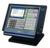
Casio QT 6000 Service Manual - Page 17
Assembly
 |
View all Casio QT 6000 manuals
Add to My Manuals
Save this manual to your list of manuals |
Page 17 highlights
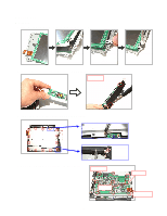
4. ASSEMBLY s QT-6000 1. Place the LCD UNIT in the frame and fix it with four screws. 2. Connect the connector and fix the inverter PCB with two screws. Screw × 2 3. Fix the LCD UNIT to the FRONT CASE with 14 screws. Fix the screws from above the earth plate. Bind the wirings for the inverter. 4. Fix the main PCB with six screws and three bosses. Screw × 6 Boss × 3 - 15 - FPC Connector
-
 1
1 -
2
-
3
-
4
-
5
-
6
-
7
-
8
-
9
-
10
-
11
-
 12
12 -
 13
13 -
 14
14 -
 15
15 -
 16
16 -
 17
17 -
 18
18 -
 19
19 -
 20
20 -
 21
21 -
 22
22 -
23
-
24
-
25
-
26
-
27
-
28
-
29
-
30
-
31
-
32
-
33
-
34
-
35
-
36
-
37
-
38
-
39
-
40
-
41
-
42
-
43
-
44
-
45
-
46
-
47
-
48
-
49
-
50
-
51
-
52
-
53
-
54
-
55
-
56
-
57
-
58
-
59
-
60
-
61
-
62
-
63
-
64
-
65
-
66
-
67
-
68
-
69
-
70
-
71
-
72
-
73
-
74
-
75
-
76
-
77
-
78
-
79
-
80
-
81
-
82
-
83
-
84
-
85
-
86
-
87
-
88
-
89
-
90
-
91
-
92
-
93
-
94
-
95
-
96
-
97
-
98
-
99
-
100
-
101
-
102
-
103
-
104
-
105
-
106
-
107
-
108
-
109
-
110
-
111
-
112
-
113
-
114
-
115
-
116
-
117
-
118
-
119
-
120
-
121
-
122
-
123
-
124
-
125
-
126
-
127
-
128
-
129
-
130
-
131
-
132
-
133
-
134
-
135
-
136
-
137
-
138
-
139
-
140
-
141
-
142
-
143
-
144
-
145
-
146
-
147
-
148
-
149
-
150
-
151
-
152
-
153
-
154
 |
 |

— 15 —
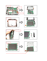
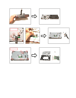
4. ASSEMBLY
■
QT-6000
1. Place the LCD UNIT in the frame and fix it with four screws.
2. Connect the connector and fix the inverter PCB with two screws.
Screw
×
2
3. Fix the LCD UNIT to the FRONT CASE with 14 screws.
Fix the screws from above the earth plate.
Bind the wirings for the inverter.
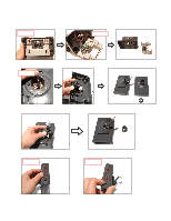
4. Fix the main PCB with six screws and three bosses.
FPC
Connector
Boss
×
3
Screw
×
6