Casio QT 6000 Service Manual - Page 22
Let the connector through the cap and fix the LCD unit with four screws.
 |
View all Casio QT 6000 manuals
Add to My Manuals
Save this manual to your list of manuals |
Page 22 highlights
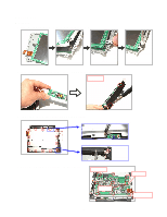
5. Fix the cap to the LCD Unit. Be careful with the position of the screw holes. 6. Fix the cap to the stand. Be careful with the direction of the cap. The height of the screw hole on the front side should be lower. 7. Let the connector through the cap and fix the LCD unit with four screws. Screw × 4 8. Connect the connector and fix the IO Unit with four screws. Connector Screw × 4 - 20 -
-
 1
1 -
2
-
3
-
4
-
5
-
6
-
7
-
8
-
9
-
10
-
11
-
12
-
13
-
14
-
15
-
16
-
 17
17 -
 18
18 -
 19
19 -
 20
20 -
 21
21 -
 22
22 -
 23
23 -
 24
24 -
 25
25 -
 26
26 -
 27
27 -
28
-
29
-
30
-
31
-
32
-
33
-
34
-
35
-
36
-
37
-
38
-
39
-
40
-
41
-
42
-
43
-
44
-
45
-
46
-
47
-
48
-
49
-
50
-
51
-
52
-
53
-
54
-
55
-
56
-
57
-
58
-
59
-
60
-
61
-
62
-
63
-
64
-
65
-
66
-
67
-
68
-
69
-
70
-
71
-
72
-
73
-
74
-
75
-
76
-
77
-
78
-
79
-
80
-
81
-
82
-
83
-
84
-
85
-
86
-
87
-
88
-
89
-
90
-
91
-
92
-
93
-
94
-
95
-
96
-
97
-
98
-
99
-
100
-
101
-
102
-
103
-
104
-
105
-
106
-
107
-
108
-
109
-
110
-
111
-
112
-
113
-
114
-
115
-
116
-
117
-
118
-
119
-
120
-
121
-
122
-
123
-
124
-
125
-
126
-
127
-
128
-
129
-
130
-
131
-
132
-
133
-
134
-
135
-
136
-
137
-
138
-
139
-
140
-
141
-
142
-
143
-
144
-
145
-
146
-
147
-
148
-
149
-
150
-
151
-
152
-
153
-
154
 |
 |

— 20 —
5. Fix the cap to the LCD Unit.
Be careful with the position of the screw holes.
6. Fix the cap to the stand.
Be careful with the direction of the cap. The height of the screw hole on the front side should be lower.
Screw
×
4
7. Let the connector through the cap and fix the LCD unit with four screws.
8. Connect the connector and fix the IO Unit with four screws.
Screw
×
4
Connector