Dell PowerConnect 6248 Configuration Guide - Page 136
CLI Example
 |
View all Dell PowerConnect 6248 manuals
Add to My Manuals
Save this manual to your list of manuals |
Page 136 highlights
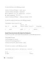
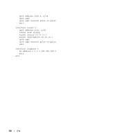
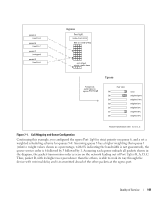
• Allocated from part of the IPv6 unicast address space • Not visible off the local link • Not globally unique Next hop addresses computed by routing protocols are usually link-local. During a transition period, a global IPv6 Internet backbone may not be available. The solution of this is to tunnel IPv6 packets inside IPv4 to reach remote IPv6 islands. When a packet is sent over such a link, it is encapsulated in IPv4 in order to traverse an IPv4 network and has the IPv4 headers removed at the other end of the tunnel. CLI Example In Figure 6-1, two devices are connected as shown in the diagram. The VLAN 15 routing interface on both devices connects to an IPv4 backbone network where OSPF is used as the dynamic routing protocol to exchange IPv4 routes. OSPF allows device 1 and device 2 to learn routes to each other (from the 20.20.20.x network to the 10.10.10.x network and vice versa). The VLAN 2 routing interface on both devices connects to the local IPv6 network. OSPFv3 is used to exchange IPv6 routes between the two devices. The tunnel interface allows data to be transported between the two remote IPv6 networks over the IPv4 network. VLAN 2 VLAN 15 Network VLAN 15 VLAN 2 Figure 6-1. IPv6 Example Device 1 console# config ip routing ipv6 unicast-routing router ospf router-id 1.1.1.1 exit ipv6 router ospf router-id 1.1.1.1 exit interface vlan 15 routing ip address 20.20.20.1 255.255.255.0 136 IPv6
-
 1
1 -
2
-
3
-
4
-
5
-
6
-
7
-
8
-
9
-
10
-
11
-
12
-
13
-
14
-
15
-
16
-
17
-
18
-
19
-
20
-
21
-
22
-
23
-
24
-
25
-
26
-
27
-
28
-
29
-
30
-
31
-
32
-
33
-
34
-
35
-
36
-
37
-
38
-
39
-
40
-
41
-
42
-
43
-
44
-
45
-
46
-
47
-
48
-
49
-
50
-
51
-
52
-
53
-
54
-
55
-
56
-
57
-
58
-
59
-
60
-
61
-
62
-
63
-
64
-
65
-
66
-
67
-
68
-
69
-
70
-
71
-
72
-
73
-
74
-
75
-
76
-
77
-
78
-
79
-
80
-
81
-
82
-
83
-
84
-
85
-
86
-
87
-
88
-
89
-
90
-
91
-
92
-
93
-
94
-
95
-
96
-
97
-
98
-
99
-
100
-
101
-
102
-
103
-
104
-
105
-
106
-
107
-
108
-
109
-
110
-
111
-
112
-
113
-
114
-
115
-
116
-
117
-
118
-
119
-
120
-
121
-
122
-
123
-
124
-
125
-
126
-
127
-
128
-
129
-
130
-
 131
131 -
 132
132 -
 133
133 -
 134
134 -
 135
135 -
 136
136 -
 137
137 -
 138
138 -
 139
139 -
 140
140 -
 141
141 -
142
-
143
-
144
-
145
-
146
-
147
-
148
-
149
-
150
-
151
-
152
-
153
-
154
-
155
-
156
-
157
-
158
-
159
-
160
-
161
-
162
-
163
-
164
-
165
-
166
-
167
-
168
-
169
-
170
-
171
-
172
-
173
-
174
-
175
-
176
 |
 |
