Epson FX 1170 User Manual - Page 138
signal is LOW., only after receipt of the ACKNLG signal or when the BUSY - head cable
 |
View all Epson FX 1170 manuals
Add to My Manuals
Save this manual to your list of manuals |
Page 138 highlights
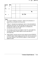
fnterface Speclflcattos Signal Direction Description GND - NC - OUT SLCT IN IN Same as for pins 19-30 Not used Pulled up to 5V through 3.3 kQ resistance The DCl/DC3 code is valid only when this signal is HIGH. This signal is factory-set to HIGH. Note: 1 The column heading "Direction" refers to the direction of signal flow as viewed from the printer. "Return" denotes the twisted-pair return, to be connected at signal ground level. For the interface wiring, be sure to use a twisted-pair cable for each signal and to complete the connection on the return side. All interface conditions are based on the TTL level. Both the rise and fall times of each signal must be less than 0.2 microseconds. Data transfer must be carried out by observing the ACKNLG or BUSY signal. Data transfer to this printer can be carried out only after receipt of the ACKNLG signal or when the BUSY signal is LOW. Technical Specifications 7-13
-
 1
1 -
2
-
3
-
4
-
5
-
6
-
7
-
8
-
9
-
10
-
11
-
12
-
13
-
14
-
15
-
16
-
17
-
18
-
19
-
20
-
21
-
22
-
23
-
24
-
25
-
26
-
27
-
28
-
29
-
30
-
31
-
32
-
33
-
34
-
35
-
36
-
37
-
38
-
39
-
40
-
41
-
42
-
43
-
44
-
45
-
46
-
47
-
48
-
49
-
50
-
51
-
52
-
53
-
54
-
55
-
56
-
57
-
58
-
59
-
60
-
61
-
62
-
63
-
64
-
65
-
66
-
67
-
68
-
69
-
70
-
71
-
72
-
73
-
74
-
75
-
76
-
77
-
78
-
79
-
80
-
81
-
82
-
83
-
84
-
85
-
86
-
87
-
88
-
89
-
90
-
91
-
92
-
93
-
94
-
95
-
96
-
97
-
98
-
99
-
100
-
101
-
102
-
103
-
104
-
105
-
106
-
107
-
108
-
109
-
110
-
111
-
112
-
113
-
114
-
115
-
116
-
117
-
118
-
119
-
120
-
121
-
122
-
123
-
124
-
125
-
126
-
127
-
128
-
129
-
130
-
131
-
132
-
 133
133 -
 134
134 -
 135
135 -
 136
136 -
 137
137 -
 138
138 -
 139
139 -
 140
140 -
 141
141 -
 142
142 -
 143
143 -
144
-
145
-
146
-
147
-
148
-
149
-
150
-
151
-
152
-
153
-
154
-
155
-
156
-
157
-
158
-
159
-
160
-
161
-
162
-
163
-
164
-
165
-
166
-
167
-
168
-
169
-
170
-
171
-
172
-
173
-
174
-
175
-
176
-
177
-
178
-
179
-
180
-
181
-
182
-
183
-
184
 |
 |
