HP Cisco MDS 9020 Cisco MDS 9500 Series Hardware Installation Guide (OL-17467- - Page 107
System Ground Location on the Cisco MDS 9506 Chassis, Step 1
 |
View all HP Cisco MDS 9020 manuals
Add to My Manuals
Save this manual to your list of manuals |
Page 107 highlights
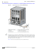
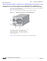
Chapter 2 Installing the Cisco MDS 9500 Series Grounding the Chassis Send documentation comments to [email protected]. Figure 2-14 System Ground Location on the Cisco MDS 9506 Chassis 1 2 99269 3 4 6 5 1 ESD socket (on switch) 2 ESD plug 3 Grounding cable 4 Screws, M4, with square cone washers 5 NRTL listed grounding lug 6 Close-up of grounding pad on switch To attach the grounding lug and cable to the chassis, follow these steps: Step 1 Step 2 Step 3 Step 4 Step 5 Step 6 Step 7 Locate the ESD socket on your chassis and attach the ESD plug. Use a wire-stripping tool to remove approximately 0.75 inches (19 mm) of the covering from the end of the grounding cable. Insert the stripped end of the grounding cable into the grounding lug. Use the crimping tool to secure the grounding cable in the grounding lug. Remove the adhesive label from the grounding pad on the chassis. Place the grounding lug against the grounding pad so that there is solid metal-to-metal contact, and insert the two M4 screws with washers through the holes in the grounding lug and into the grounding pad. Ensure that the lug and cable do not interfere with other equipment. Prepare the other end of the grounding cable and connect it to an appropriate grounding point in your site to ensure adequate earth ground. OL-17467-02 Cisco MDS 9500 Series Hardware Installation Guide 2-27
-
 1
1 -
2
-
3
-
4
-
5
-
6
-
7
-
8
-
9
-
10
-
11
-
12
-
13
-
14
-
15
-
16
-
17
-
18
-
19
-
20
-
21
-
22
-
23
-
24
-
25
-
26
-
27
-
28
-
29
-
30
-
31
-
32
-
33
-
34
-
35
-
36
-
37
-
38
-
39
-
40
-
41
-
42
-
43
-
44
-
45
-
46
-
47
-
48
-
49
-
50
-
51
-
52
-
53
-
54
-
55
-
56
-
57
-
58
-
59
-
60
-
61
-
62
-
63
-
64
-
65
-
66
-
67
-
68
-
69
-
70
-
71
-
72
-
73
-
74
-
75
-
76
-
77
-
78
-
79
-
80
-
81
-
82
-
83
-
84
-
85
-
86
-
87
-
88
-
89
-
90
-
91
-
92
-
93
-
94
-
95
-
96
-
97
-
98
-
99
-
100
-
101
-
 102
102 -
 103
103 -
 104
104 -
 105
105 -
 106
106 -
 107
107 -
 108
108 -
 109
109 -
 110
110 -
 111
111 -
 112
112 -
113
-
114
-
115
-
116
-
117
-
118
-
119
-
120
-
121
-
122
-
123
-
124
-
125
-
126
-
127
-
128
-
129
-
130
-
131
-
132
-
133
-
134
-
135
-
136
-
137
-
138
-
139
-
140
-
141
-
142
-
143
-
144
-
145
-
146
-
147
-
148
-
149
-
150
-
151
-
152
-
153
-
154
-
155
-
156
-
157
-
158
-
159
-
160
-
161
-
162
-
163
-
164
-
165
-
166
-
167
-
168
-
169
-
170
-
171
-
172
-
173
-
174
-
175
-
176
-
177
-
178
-
179
-
180
-
181
-
182
-
183
-
184
-
185
-
186
-
187
-
188
-
189
-
190
-
191
-
192
-
193
-
194
-
195
-
196
-
197
-
198
-
199
-
200
-
201
-
202
-
203
-
204
-
205
-
206
-
207
-
208
-
209
-
210
-
211
-
212
-
213
-
214
-
215
-
216
-
217
-
218
-
219
-
220
-
221
-
222
-
223
-
224
-
225
-
226
-
227
-
228
-
229
-
230
-
231
-
232
-
233
-
234
-
235
-
236
-
237
-
238
-
239
-
240
-
241
-
242
-
243
-
244
-
245
-
246
-
247
-
248
-
249
-
250
-
251
-
252
-
253
-
254
-
255
-
256
-
257
-
258
-
259
-
260
-
261
-
262
-
263
-
264
-
265
-
266
-
267
-
268
-
269
-
270
-
271
-
272
-
273
-
274
-
275
-
276
-
277
-
278
-
279
-
280
-
281
-
282
-
283
-
284
-
285
-
286
-
287
-
288
 |
 |
