HP Cisco MDS 9020 Cisco MDS 9500 Series Hardware Installation Guide (OL-17467- - Page 143
Step 2, Warning, Caution, FAN OK LED is green.
 |
View all HP Cisco MDS 9020 manuals
Add to My Manuals
Save this manual to your list of manuals |
Page 143 highlights
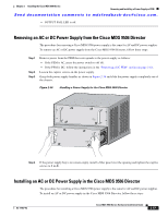
Chapter 2 Installing the Cisco MDS 9500 Series Removing and Installing a Power Supply or PEM Send documentation comments to [email protected]. Step 2 Step 3 Step 4 Step 5 Ensure that the system (earth) ground connection has been made. See the "System Grounding" section on page 2-17. Grasp the power supply handle with one hand, place your other hand underneath the power supply, and slide the power supply into the power supply bay, ensuring that it is fully seated in the bay. Tighten the captive screw on the power supply to 8 in-lb. Remove the two screws securing the terminal block cover and slide the cover off of the terminal block. Note Use 90°C copper conductors for North American installations. Step 6 Step 7 Loosen the screws inside the terminal block and attach the DC cables to the screws. The wire must be copper, and sized per local and national installation requirements. Connect the DC cables to the terminal block in the following order: • Ground • Negative (-) • Positive (+) Warning When installing or replacing the unit, the ground connection must always be made first and disconnected last. Statement 1046 Caution The DC return connection (Negative (-)) to this system is to remain isolated from the system frame and chassis (DC-I). Step 8 Reinstall the terminal block cover after ensuring that all cable connections are secure and tighten the screws holding the terminal block to the power supply. Caution Reinstall the terminal block cover to prevent a short circuit or shock hazard. Caution In a system with dual power supplies, connect each power supply to a separate source. In case of a line failure, the second source will most likely still be available. Step 9 Step 10 Remove the tape from the circuit breaker switch handle and provide power by moving the handle to the on (|) position.Turning the power switch on also locks the power supply in the chassis. Verify power supply operation by checking that the power supply LEDs are in the following states: • INPUT OK LED is green. • FAN OK LED is green. • Output fail LED is off. OL-17467-02 Cisco MDS 9500 Series Hardware Installation Guide 2-63
-
 1
1 -
2
-
3
-
4
-
5
-
6
-
7
-
8
-
9
-
10
-
11
-
12
-
13
-
14
-
15
-
16
-
17
-
18
-
19
-
20
-
21
-
22
-
23
-
24
-
25
-
26
-
27
-
28
-
29
-
30
-
31
-
32
-
33
-
34
-
35
-
36
-
37
-
38
-
39
-
40
-
41
-
42
-
43
-
44
-
45
-
46
-
47
-
48
-
49
-
50
-
51
-
52
-
53
-
54
-
55
-
56
-
57
-
58
-
59
-
60
-
61
-
62
-
63
-
64
-
65
-
66
-
67
-
68
-
69
-
70
-
71
-
72
-
73
-
74
-
75
-
76
-
77
-
78
-
79
-
80
-
81
-
82
-
83
-
84
-
85
-
86
-
87
-
88
-
89
-
90
-
91
-
92
-
93
-
94
-
95
-
96
-
97
-
98
-
99
-
100
-
101
-
102
-
103
-
104
-
105
-
106
-
107
-
108
-
109
-
110
-
111
-
112
-
113
-
114
-
115
-
116
-
117
-
118
-
119
-
120
-
121
-
122
-
123
-
124
-
125
-
126
-
127
-
128
-
129
-
130
-
131
-
132
-
133
-
134
-
135
-
136
-
137
-
 138
138 -
 139
139 -
 140
140 -
 141
141 -
 142
142 -
 143
143 -
 144
144 -
 145
145 -
 146
146 -
 147
147 -
 148
148 -
149
-
150
-
151
-
152
-
153
-
154
-
155
-
156
-
157
-
158
-
159
-
160
-
161
-
162
-
163
-
164
-
165
-
166
-
167
-
168
-
169
-
170
-
171
-
172
-
173
-
174
-
175
-
176
-
177
-
178
-
179
-
180
-
181
-
182
-
183
-
184
-
185
-
186
-
187
-
188
-
189
-
190
-
191
-
192
-
193
-
194
-
195
-
196
-
197
-
198
-
199
-
200
-
201
-
202
-
203
-
204
-
205
-
206
-
207
-
208
-
209
-
210
-
211
-
212
-
213
-
214
-
215
-
216
-
217
-
218
-
219
-
220
-
221
-
222
-
223
-
224
-
225
-
226
-
227
-
228
-
229
-
230
-
231
-
232
-
233
-
234
-
235
-
236
-
237
-
238
-
239
-
240
-
241
-
242
-
243
-
244
-
245
-
246
-
247
-
248
-
249
-
250
-
251
-
252
-
253
-
254
-
255
-
256
-
257
-
258
-
259
-
260
-
261
-
262
-
263
-
264
-
265
-
266
-
267
-
268
-
269
-
270
-
271
-
272
-
273
-
274
-
275
-
276
-
277
-
278
-
279
-
280
-
281
-
282
-
283
-
284
-
285
-
286
-
287
-
288
 |
 |
